MITX-6771 Technical Specification Manual Version: R1.
Revisions Version Description of Version Date Completed R1.
Preface This Technical Specification Manual (TSM) specifies the board layout, components, connectors, and the I/O connection ports, motherboards features. Intended Audience The TSM is intended to provide detailed, technical information about the MITX-6771 and its components to the vendors, system integrators, and other engineers and technicians who need this level of information. It is specifically not intended for general audiences.
1. Introduction 1.1 Product introduction. The MITX-6771 is a Thin mini-ITX Intel Bay Trail platform based motherboard. It has a Intel Celeron Processor J1900 (2M Cache, up to 2.42 GHz) on board with two SO-DIMM slots support up to 8G of DDR3L RAM. The I /O interfaces include: HDMI, VGA, LVDS header, Gigabit Ethernet, Mic-in, Audio-out, 5x USB USB2.0, 1x USB3.0, 2x COM, 1x mini-PCIE+ USB with SIM slot and 1x mSATA slot.
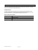
2. Product Description 2.1 Specification Table 1 summarizes the major features of the board. Table 1. Specification Essentials Platform Codename Form Factor Processor Chipset BIOS System Memory Ethernet Storage Expansion Power Bay Trail mini-ITX Intel Celeron J1900 2.42 GHz SoC AMI 2x 204-Pin DDR3L SO-DIMM, up to 4GB each 1x RJ45 ,Realtek RTL8111F, GbE x1, (OEM option of second GbE x 1) 1x SATA 3Gb/s, 1x mSATA (mini-PCIe) 1x mini-PCIe with USB + SIM ,1x PCIe x1 slot 12/19V DC 2.
2.2 Board Layout Figure 1 shows the location of the major components on the top-side of the MITX-6771. D A B C E DD CC F BB AA G Z H Y X I W V J U K Figure 1: MITX-6771 (Top) T L S R Q P O N Figure 1.
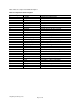
Table 2 lists the components identified in Figure 1 Table 2.
2.3 Back Panel Connectors A B C D E Figure 2. Back Panel Connectors Table 3 lists the components identified in Figure 2 Table 3. Components Show in Figure 2 Item A B C D E F G H Description DC input jack USB2.0 ports LAN connector VGA connector USB2.
2.4 Dimension 170mm/ 6.7" 170mm/ 6.7" Figure 3.
2.5 Block Diagram Figure 4 is a block diagram of the major functional areas of the board. Figure 4.
3. Technical Reference 3.1 Connectors and Headers (TOP) Figure 5 shows the locations of the connectors and headers on the top-side of the board. Figure 5.
Table 4 - 29 lists the connectors and headers identified in Figure 5. Table 4. Front panel audio header (Figure. 5. A) Pin 1 Signal Name MIC_L Description Front Panel MIC in Left 2 3 4 5 6 7 8 9 10 GND MIC_R N/A FRONT_R F_IO_SENCE GND N/A FRONT_L F_IO_SENCE Ground Front Panel MIC in Right Front Panel Audio out Right Front Audio Jack detection Ground Front Panel Audio out Left Front Audio Jack detection Table 5. VGA header (Figure. 5.
8 9 10 11 12 13 14 15 VVC_5V VVC_5V GND GND GND VVC_12V VVC_12V VVC_12V Table 8. SATA power connector 2 (Figure. 5. E) Pin 1 2 3 4 Signal Name 5V GND GND 12V Table 10. SATA data connector (Figure. 5. G) Pin 1 2 3 4 5 6 7 8 9 Signal Name GND SATA_TXP SATA_TXN GND SATA_RXN SATA_RXP GND GND GND Table 11. 3-wire CPU fan header (Figure. 5. H) Pin 1 2 3 Signal Name GND 12V DC FAN_TAC Table 12. 3-wire system fan header (Figure. 5.
Table 13. Clear CMOS jumper (Figure. 5. J) Pin Description 1, 2 Open Normal 1, 2 Close Clear CMOS Table 14. LVDS connector (Figure. 5. K) Pin 1 3 5 7 9 11 13 15 17 19 21 23 25 27 29 Signal Name LVDS_PWR LVDS_PWR GND LVDS_TX_A0N LVDS_TX_A1N LVDS_TX_A2N GND LVDS_TX_CLKAN LVDS_TX_A3N LVDS_TX_B0N LVDS_TX_B1N LVDS_TX_B2N GND LVDS_TX_CLKBN LVDS_TX_B3N Pin 2 4 6 8 10 12 14 16 18 20 22 24 26 28 30 Table 15. Flat panel LVDS voltage power jumper (Figure. 5. L) Pin Description 1, 2 Close 12V 3.
Table 17. Panel Switch header (Figure. 5. N) Pin 1 2 Signal Name DISPLAY_ON/OFF GND Table 18. Flat panel backlight power selection header (Figure. 5. O) Pin Description 1, 2 Close 12V 2, 3 Close VDC Table 19. Front panel header (Figure. 5. P) Pin 1 2 3 4 5 6 7 8 9 10 Signal Name HD_LEDPWR_LEDHD-LED+ PWR_LED+ RESET Power Button GND GND NC Key Table 20. Serial port headers (Figure. 5. Q) Pin 1 2 3 4 5 6 7 8 9 10 Signal Name NDCD MSIN NSOUT NDTR GND NDSR NDSS NCTS NRI N/A Table 21.
13 15 17 19 21 23 25 P_D5 P_D6 P_D7 ACKJ BUSY PE SLCT 14 16 18 20 22 24 26 GND GND GND GND GND LPT_DET# NC Table 22. Front USB 2.0 headers (Figure. 5. S) Pin 1 2 3 4 5 6 7 8 9 10 Signal Name VCC VCC USBUSBUSB+ USB+ GND GND Key GND Table 23. KS/MS (Figure. 5. T) Pin 1 2 3 4 5 6 Signal Name PS2POWER KDAT KCLK MDAT MCLK GND Table 24. PCI Express Full/Half-Mini card slot (Figure. 5. F, U) Pin 1 2 3 4 5 6 7 8 9 10 11 12 M-PCIE WAKE# +3.3 V aux Reserved GND Reserved 1.
13 14 15 16 17 18 19 20 21 22 23 24 25 26 27 28 29 30 31 32 33 34 35 36 37 38 39 40 41 42 43 44 45 46 47 48 49 50 51 52 REFCLK+ Reserved GND Reserved Reserved GND Reserved Reserved GND PERST# PERn0 +3.3 V aux PERp0 GND GND +1.5 V GND SMB_CLK PETn0 SMB_DATA PETp0 GND GND USB_DGND USB_D+ +3.3 V aux GND +3.3 V aux LED_WWAN# Reserved LED_WLAN# Reserved LED_WPAN# Reserved +1.5V Reserved GND Reserved +3.3 V aux (mSATA) GND (mSATA) 3.3 V (mSATA) 3.
3 4 5 6 7 8 9 10 11 12 13 14 15 16 17 18 19 20 NC GND NC NC GND NC NC NC DATA+ DATAGND USB3_TXP0_R USB3_TXN0_R GND USB3_TXP0_R USB3_TXN0_R USB-PWR NC Table 27. Internal stereo speakers connector (Figure. 5. X) Pin 1 2 3 4 Signal Name LOUTLOUT+ ROUT+ ROUT- Table 28. S/PDIF header (Figure. 5.
4. BIOS Features 4.1 Introduction The board uses an AMI BIOS that is stored in the Serial Peripheral Interface Flash Memory (SPI Flash) and can be updated using a disk-based program. 4.2 BIOS Updates The BIOS can be updated using a flash utility which requires booting from DOS. . Using this utility, the BIOS can be updated from a file on a hard disk, a USB drive (a flash drive or a USB hard drive). Ask technical support for the utility and up-to-date BIOS file.
PPM Cfg Discard Changes and Reset IDE Cfg Miscellaneous Cfg Save Options Boot Override Network Stack Cfg Launch EFI Shell from filesystem device CSM Cfg Realtek PCIe GBE Family Controller Reset System with TXE disable Mode Table 31.
Table 33-1.
4 PWM 8 PWM Celsius degree Table 33-3.
Custom settings Table 33-4. Advanced - PPM Configuration Main Advanced Chipset Security Boot Save& Exit PPM Configuration Item Field EIST Disabled Enabled CPU C State Report Enhanced C State Max CPU C-State Soix Description Select to Enable Intel EIST (Enhanced Intel SpeedStep Technology) Disabled Enabled Disabled Enabled C7 C6 C1 Disabled Enabled Select to Enable C State Report Select to Enable Enhanced C State Select C State Mode Select to Enable Soix active idle state Table 33-5.
Main Advanced Chipset Security Boot Save& Exit Miscellaneous Configuration Item Field Windows 8.X Android Windows 7 OS Selection Description Select OS to be installed Table 33-7.
Item Field PCI mode Disabled On off Enabled Disabled Auto Smart Auto Enabled Disabled Enabled Disabled Enabled Disabled Enabled Disabled Enabled Disabled Enabled Disabled Enabled Disabled Description Select Enabled USB OTG Port support Select Enabled USB VBUS support Item Field Restore AC Power Loss Power off Power on Last State Description Select Power-Off for the system power to remain off after a power loss. Select PowerOn for the system power to be turned on after a power loss.
Item Field Save Changes and Exit Yes/ No Discard Changes and Exit Yes/ No Save changes and Reset Yes/ No Save Options Item Field Save Changes Yes/ No Discard changes Yes/ No Restore Defaults Yes/ No Save as User Defaults Yes/ No Restore User Defaults Yes/ No Description Select this option to leave the BIOS setup utility and reboot the computer for the new system configuration parameters can take effect Select this option to quit the BIOS Setup without making any permanent changes to the