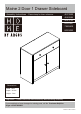
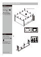
Maine 2 Door 1 Drawer Sideboard Assembly Instructions - 461/3369 Please keep for future reference 464/6989 464/3724 803/2991 798/9409 803/3093 Dimensions Width - 80cm Depth - 35.
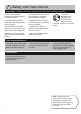
Safety and Care Advice Important – Please read these instructions fully before starting assembly • Check you have all the components and tools listed on the following pages. • During assembly do not stand or put weight on the product, this could cause damage. • Remove all fittings from the plastic bags and separate them into their groups. • Assemble the item as close to its final position (in the same room) as possible.
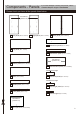
Components - Panels If you have damaged or missing components, call the Customer Helpline: Argos = 0345 6400800 Please check you have all the panels listed below Pilot holes for guidance only 1 Left panel (34.9 x 72.4cm) 2 Right panel (34.9 x 72.4cm) 3 Back panel (79.4 x 66.5cm) 10 Drawer front panel (76.1 x 16cm) 4 Top panel (80.1 x 35cm) 11 Drawer back panel (71.9 x 11.8cm) Pilot holes for guidance only 5 Bottom panel (76.8 x 32.3cm) 12 Drawer bottom panel (74.3 x 28.
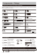
Components - Fittings Please check you have all the fittings listed below Note: The quantities below are the correct amount to complete the assembly. In some cases more fittings may be supplied than are required.
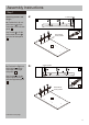
Assembly Instructions Step 1 Attaching runners and hinges a: 2 Holes upside 2 A a: Position the Left out- A A K side runners K in from front edge of the Left side panel 2 . K A Use Screws A to fix the Left outside runners K onto the Left side panel 2 . A K A Pilot holes for runner position 2 2 b: Position the Right out- side runners M in from front edge of the Right side panel 1 . b: 2 Holes upside A A 1 A M Use Screws A to fix the Right outside runners M onto the Right side panel 1 .
Assembly Instructions Step 1 - continued c: Use Screws B to fix the Door hinges J ‘back plates’ onto the Left side panel 2 . c: G Insert Dowels F into the Left side panel 2 . G Screw Locking pins G into the Left side panel 2 . B B F J B Note: Insert locking pins as far as shown. Do not over tighten. d: Use Screws B to fix the Door hinges J ‘back plates’ onto the Right side panel 1 . J J G 2 G d: G Insert Dowels F into the Right side panel 1 .
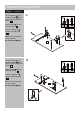
Assembly Instructions Step 2 Attaching bottom panel a: C C a: Use Screws C to fix Plastic supports the Front panel E 8 onto . Use Screws C to fix Front panel 8 onto the Bottom panel 5 . C Note: of the Plastic supports E even with the edges of Front panel 8 and Bottom panel 5 . Insert Dowels Bottom panel F 5 C 8 E C into the . E C E C 8 C E F E 5 E F b: Insert Dowels Middle panel 7 . F into b: F 7 F Continued on next page.
Assembly Instructions Step 2 - continued c: Carefully locate the Left panel 1 onto the Middle panel 7 and Bottom panel 5 . c: H Insert 3 Locking nuts H into the Middle panel 7 and Bottom panel 5 . Use a screwdriver to turn Locking nuts H clockwise to lock. 1 H H 7 5 H d: Carefully locate the Right panel unit. 2 onto the Insert 3 Locking nuts into the unit. d: H H Use a screwdriver to turn Locking nuts H clockwise to lock.
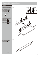
Assembly Instructions Step 3 a: Attaching top panel G a: Screw Locking pins G into the Top panel 4 . Note: Insert locking pins G as far as shown. Do not over tighten. G G 4 G b: Carefully locate the Top panel 4 onto the unit. Insert 4 Locking nuts into the unit. b: H H Use a screwdriver to turn Locking nuts H clockwise to lock.
Assembly Instructions Step 4 Fixing back panel Attach Back panel using nails P . P Unfinished back surface 3 Important: The unit MUST be ‘square’ when back is attached. 3 Step 5 a: Drawer assembly a: Screw Locking pins G G into the Drawer front panel 10 . G Note: Insert locking pins as far as shown. Do not over tighten. G G G 10 Continued on next page.
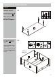
Assembly Instructions Step 5 - continued b: Fix Drawer right panel 14 , Drawer support 15 and Drawer left panel 13 onto Drawer front panel 10 . b: I Insert 5 Locking nuts I into the Drawer right panel 14 , Drawer support 15 and Drawer left panel 13 . Finished front edge Use a screwdriver to turn Locking nuts H clockwise to lock. 13 I I 15 14 I c: Carefully slide the Drawer bottom panel into the grooves. 12 I 10 I c: Unfinished back surface 12 13 15 14 10 Continued on next page.
Assembly Instructions Step 5 - continued d: Position the Drawer back panel 11 onto the unit using Screws D . d: D D 11 12 15 D e: Turn the unit upside down carefully. D 14 e: A N Use Screws A to fix the Left inside runners N and Right inside runners L onto the unit. A 12 A L A A A 10 8 f: Attach Handles Drawer front panel using Screws D .
Assembly Instructions Step 6 a: Attaching shelf R With help, carefully stand unit upright. Q Warning: The unit is heavy. Lift with care. a: Slide Support covers onto Shelf supports Q . Insert Shelf supports Q (Support covers R are included) into the unit. Ensure they are well fitted before inserting the Shelves. R 2 R + Q 1 Note: Set the shelf R + Q supports to the desired height. b: Slide Shelf the unit.
Assembly Instructions Step 8 Hanging doors a: With help, slot Door hinges J onto ‘hinge plates’. b: Tighten screw shown to lock hinges in position. Repeat a and b for opposite door. See ‘Hinge adjustment’ in step 10 if the doors need adjusting.
Assembly Instructions Step 9 Hinge adjustment a: To move doors up or down: loosen screws shown and move doors to suit. Once doors are aligned, re-tighten Screws B . a: B Door b: To move doors in or out: loosen screw shown and move doors to suit. Re-tighten screws. b: Door c: To move doors left or right: loosen screw shown and move doors to suit. Re-tighten screws.
Assembly Instructions Step 10 Fixing to wall Warning: In order to prevent overturning, this product must be used with the wall attachment device provided. Use Screws(2 pcs) C to fix Wall straps(2 pcs) U onto the unit. Note: Wall plugs supplied are for solid wall only. wall U T be used for your wall, seek professional advice if in doubt U C U U Top panel With help, move this product into position. Warning: Back panel This product is heavy. Lift with care.
A Guide to - Wall Mounting & Fixings Important: When drilling into walls always Important note: If plastic wall plugs are supplied with your product: check that there are no hidden wires or pipes etc. Make sure that the screws and wall plugs being used are suitable for supporting your unit. Consult a qualified tradesperson if you are unsure. Hints: - these are only suitable for use in masonry walls. If you are in any doubt about the correct wall plugs for your wall, seek professional advice.