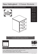
New Hallingford - 3 Drawer Bedside Assembly Instructions - Please keep for future reference 274/4917 266/7379 266/4509 258/7693 266/2910 616/9749 618/4999 601/6737 620/9379 618/6959 More help is available throughout this booklet by scanning in the QR codes or typing in the links Dimensions Width - 37.5cm Depth - 40cm Height - 58cm MADE IN BRITAIN Important - Please read these instructions fully before starting assembly If you need help or have damaged or missing parts, please visit www.argos-support.co.
Safety and Care Advice Important - Please read these instructions fully before starting assembly • Warning: This unit weighs approximately 14kgs. Please lift with care. • Make sure you have enough space to layout the parts before starting. • Check you have all the components and tools listed on pages 2 and 3. • Do not stand or put weight on the product, this could cause damage. • Remove all fittings from the plastic bags and separate them into their groups.
Components - Panels If you need help or have damaged or missing parts, please visit www.argos-support.co.uk or email: Help@ClickSpares.co.uk (quoting your original order number) Alternatively, call the Spares Helpline on: 0370 112 1928.
Components - Fittings If you need help or have damaged or missing parts, please visit www.argos-support.co.uk or email: Help@ClickSpares.co.uk (quoting your original order number) Alternatively, call the Spares Helpline on: 0370 112 1928. For any other queries please contact the Customer Helpline on: 0345 640 2020 Please check you have all the fittings listed below Note: The quantities below are the correct amount to complete the assembly. In some cases more fittings may be supplied than are required.
Assembly Instructions Step 1 Prepare the 3 drawer fronts Screw 2 metal dowels B into the holes shown on the back of each drawer front 5 . Drawer Assembly www.youtube.com/watch?v=3fYL5zB6ZYQ B B x3 B 5 Note: Tighten metal dowels up fully against the panels. Step 2 Prepare the drawer sides Insert a small locking cam nut C into the hole shown on the left drawer side 6 and right drawer side 7 . C C C 7 6 x3 Note: The arrow on the locking cam nut must point towards the hole in the edge of the panel.
Assembly Instructions Step 4 Fit the drawer base 9 Slide the drawer base 9 down the grooves in the drawer sides 6 and 7 and down into the groove in the drawer front 5 . x3 7 6 5 Step 5 E Fit the drawer back Fit the drawer back 8 between the drawer sides 6 and 7 . Make sure that the drawer base 9 fits into the groove in the drawer back 8 . E 8 E 7 E 9 6 x3 Hold the drawer back 8 in position and tap the knock-in pegs E through the holes in the drawer sides 6 and 7 .
Assembly Instructions Fixing Bottom Mounter Runners https://www.youtube.com/watch?v=Z6lGMy19h7Q Step 8 Turn the 3 drawer assemblies over. Runners must be pushed up against the drawer front Fit runner K d , marked with ‘DR’, to the bottom edge of the right drawer side 7 , as shown, making sure that it is pushed up against the back of the drawer front .5 . Use a bradawl to mark the fixing positions, then secure with 2 screws I .
Assembly Instructions Fixing Bottom Mounter Runners https://www.youtube.com/watch?v=Z6lGMy19h7Q Step 10 Prepare the left side The 1st screw H uses the 1st hole in from the front of the runner. 1st screw H Finished front edge a: Fit 3 CL runners K a to the left side 1 . K a CL H Finished front edge H H H H H L C The 2nd and 3rd screws .H use the holes that line up with the other panel holes. H L C H H L C a: K a K a 1 K a b: Fit a screw I into the hole at the top of the runners K a .
Assembly Instructions Step 11 Prepare the right side a: H H H H H H K b R C Fit 3 CR runners K b to the right side 2 . H H R C a: H R C K b 2 The 1st screw H uses the 1st hole in from the front of the runner. K b Finished front edge Finished front edge 1st H screw The 2nd and 3rd screws .H use the holes that line up with the other panel holes. K b CR b: Fit a screw I into the hole at the top of the runner K b .
Assembly Instructions Step 13 Fit the left side 4 CR 1 CR Use a screwdriver to tighten the 2 large locking cam nuts D fitted to the rails 4 . CR Push the left side 1 onto the 2 rails 4 . 4 Step 14 Plain chipboard surface B Prepare the top B Screw 2 metal dowels B into the top 3 . 3 Shaped front edge Step 15 Fit the top 3 Push the top 3 onto the 2 sides 1 and 2 . 2 CR CR 9 CR Use a screwdriver to tighten the 2 large locking cam nuts D fitted to the sides 1 and 2 .
Assembly Instructions Step 16 Squaring up a Chest and fitting the Back Panel www.youtube.com/watch?v=FeaI6541z7o Fit the back a: Square up the unit by making sure that measurement x to x equals y to y. b: Place the back a: The measurement from top corner X to bottom corner X must be equal to the measurement from top corner Y to bottom corner Y b: 10 onto the unit. x F Nail F around the outside edges of the back 10 . y CR Note: Nails should be spaced about 150mm apart.
Assembly Instructions Step 18 Fixing Bottom Mounter Runners https://www.youtube.com/watch?v=Z6lGMy19h7Q Fit the drawers Slide the wheels of the runners fitted to the drawers, over the wheels of the runners fitted to the side panels and push the drawers into position. Assembly is complete Side panel Drawer If you need help or have damaged or missing parts, please visit www.argos-support.co.uk or email: Help@ClickSpares.co.