
Manual
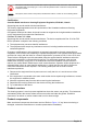

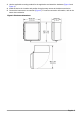
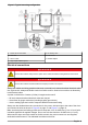

Figure 1 Product components
1 Enclosure 8 Lock washer
2 Voltage barrier (sc100) 9 Bolt, hex head, slotted
3 Screw, barrier hold-down 10 Nut, hex
4 Voltage barrier (sc200) 11 Bracket
5 Tab, wall mounting 12 Bracket
6 Screw, flat head, slotted 13 Uni-strut
7 Screw, pan head, slotted
Installation
D A N G E R
Multiple hazards. Only qualified personnel must conduct the tasks described in this section of the
document.
Instrument mounting
N O T I C E
If the instrument is installed in direct sunlight, the operating temperature might rise above its specified limit and
the compressor will not start. Install the instrument in an indoor or outdoor location that is not in direct sunlight.
1. Install the instrument near the installed sensor (Figure 5). Do not extend the air delivery tubing
beyond 7.6 m (25 ft). This keeps the capacity of the system the same and does not decrease the
response time for the air delivery.
2. Mount the instrument in a location where the ambient temperature will not be more than the
instrument temperature limits. Refer to Specifications on page
3.
6 English