DOC023.52.90140 NO3D sc Nitrate Sensor USER MANUAL 12/2008, Edition 1A © HACH -LANGE Company, 2008. All rights reserved.
Table of Contents Section 1 Specifications ........................................................................................................................ 5 1.1 Dimensions ................................................................................................................................... 6 Section 2 General Information............................................................................................................... 7 2.1 Safety information ...............................
Table of Contents Section 10 Certification ........................................................................................................................43 Appendix A Modbus Register ..............................................................................................................45 Index .......................................................................................................................................................
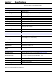
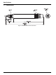
Section 1 Specifications These are subject to change without notice. General Information Measuring method Ion-selective electrodes for nitrate and chloride, pHD reference electrode and temperature sensor Measuring range 0.1 to 1000 mg/L [NO3–N] and 0.1 to 1000 mg/L [Cl-] Minimum detection limit 0.5 mg/L [NO3–N]1 Precision 5% of the measured value + 0.2 mg/L1 Reproducibility 5% of the measured value + 0.
Specifications 1.
Section 2 General Information 2.1 Safety information Please read this entire manual before unpacking, setting up, or operating this equipment. Pay attention to all danger and caution statements. Failure to do so could result in serious injury to the operator or damage to the equipment. To ensure that the protection provided by this equipment is not impaired, do not use or install this equipment in any manner other than that specified in this manual. 2.1.
General Information 2.2 General sensor information The sensor was developed for use in municipal waste water applications. The NO3D sc sensor (see Figure 2) with ion-selective electrode (ISE sensor) is a continuous online process sensor for the measurement of nitrate directly in the tank. It operates without reagents and requires no further processing of the sample. The nitrate ions are measured using an ion-selective electrode.
General Information 2.3 Theory of operation The NO3D sc sensor utilizes ion-selective electrode technology to measure nitrate ions (NO3-) in a waste water sample. Well-known interferences of temperature and chloride are compensated by using appropriate built-in sensors. The reference electrode is a differential pH technology and does not have direct contact with the process and therefore, it is particularly stable against drift.
General Information 10
Section 3 Installation Important Note: Only qualified personnel should conduct the tasks described in this section of the manual. 3.1 Unpacking the sensor Remove the sensor from the shipping container and inspect the sensor for damage. Verify that all items listed in Figure 4 are included. If any items are missing or damaged, contact the manufacturer or distributor.
Installation 4. Connect the sensor cartridge to the sensor (see 3.3 Sensor assembly on page 13). Important Note: The sensor cartridge only fits correctly in the sensor adapter in one position. Pay attention to the markings on the sensor cartridge and on the sensor adapter (see Figure 8 on page 14).
Installation Figure 6 Storage container for sensor cartridge1 1 Storage container 3 Sensor cartridge 2 Black gasket (remove before installation) 4 Cap 1 Save items 1, 2 and 4 for sensor storage. 3.3 Sensor assembly Important Note: Avoid touching the membranes on the sensor cartridge or damage to the sensor may occur. 1. Remove the black gasket. 2. Ensure that the opaque gasket is in place in the sensor adapter. The opaque gasket will be between the sensor and the sensor cartridge.
Installation Figure 7 Sensor cartridge 1 Make sure that this end remains wet 2 Make sure that the contacts on this end stay dry Figure 8 Sensor assembly 1 Locking ring 4 Sensor adapter 2 Sensor cartridge 5 Sensor housing 3 Alignment arrows 6 Opaque gasket 14
Installation Figure 9 Cap of the storage container as a tool/screwing aid for the locking ring 1 Cap 2 Locking ring 3.4 Installation of the cleaning unit (optional) To install the cleaning unit on the sensor, refer to the installation instructions for the cleaning unit (section 7.4 on page 37). The cleaning interval can be set using the relay control of the sc controller. Select RTC (Real Time Clock) as the signal source. 3.
Installation Figure 10 Example of sensor installation with Rail Mount Kit 16
Installation 3.6 Connect the sensor to the sc controller (non-hazardous location) with quick-connect fittings The sensor cable is supplied with a keyed quick-connect fitting for easy attachment to the controller (see Figure 11 on page 17). Retain the connector cap to seal the connector opening in case the sensor must be removed. Optional extension cables may be purchased to extend the sensor cable length. 1. Unscrew the protective cap from the socket on the controller. 2.
Installation 18
Section 4 Operation 4.1 Using an sc controller Before using the sensor in combination with an sc controller, refer to the controller user manual for navigation information. 4.2 Sensor setup When a sensor is installed for the first time, the serial number of the sensor is displayed as the sensor name. The sensor name can be changed as follows: 1. Select MAIN MENU. 2. From the Main Menu, select SENSOR SETUP and confirm. 3. Select the appropriate sensor if more than one sensor is attached and confirm. 4.
Operation 4.5 Sensor setup menu SELECT SENSOR (if there is more than one sensor) CALIBRATE Note: If once a calibration method is chosen the entries will be displayed in the first submenu of the calibrate menu. CAL.CONFIG. Select SENSOR CODE, MATX1, MATX1 CL-, MATX2, MATX2 CL-, VALUE CORR, PREVIOUS CAL or FACTORY CAL -orCAL.CONFIG.>SENSOR CODE DATE Displays the date of sensor cartridge start up SENSOR CODE Display and entry of the sensor code -orCAL.CONFIG.
Operation 4.5 Sensor setup menu (continued) CALIBRATE(continued) Value correction (see section 4.6.3.5 on page 27) Once value correction is complete, the correction data are displayed in the form of the MATX2 CAL.CONFIG.
Operation 4.
Operation which includes a multi-point nitrate and chloride calibration and the cross sensitivity of chloride on nitrate. When the code is entered, the sensor is completely calibrated. It is recommended to perform a matrix correction to correct the cartridge on the specific matrix. Please use the default sensor code, if the specific sensor code is not available. To change the sensor code: 1. Select SENSOR SETUP>NO3D SC> CALIBRATE>CAL.CONFIG.>SENSORCODE 2. Enter the 16 character sensor code. 3.
Operation 4.6.3 Matrix correction Note: Perform laboratory values or comparative values with cuvette tests timely or stabilized the sample, to avoide a modification of the sample concentration. In 7.3 Validation accessories on page 37 you can find recommended tests which can be used for laboratory measurements. Note: Laboratory comparison or verification samples are time sensitive. Perform analysis of these samples as quickly as possible to minimize the potential for a bias or interference in the results.
Operation READING STABLE? NO3–N: DRIFT CLDRIFT The currently measured nitrate and chloride values are displayed. The drift indicates whether the measured value is stable. 4. Wait until the measured value is stable and confirm by pressing ENTER (Drift should be < 0.03 mg/L). The values for nitrate and chloride are saved. 5. Immediately after saving, take a water sample for laboratory analysis from as close to the sensor as possible. 6.
Operation After determining the laboratory reference value, proceed as follows: 7. Select SENSOR SETUP>NO3D SC>CALIBRATE> SET NO3–N CONC. 8. Enter the laboratory value (reference value) for NO3–N and press ENTER to confirm. 9. Select MEAS CONC 2 and repeat the sequence from Point 4 to 8 for the second value after a concentration change of at least half a decade. 10. By confirming the second laboratory value, the Matrix2 correction is activated. 4.6.3.
Operation 4.6.3.5 Value correction Value correction offers the option of subsequently correcting a matrix at two different concentrations. Take several samples on various days with different concentrations and perform an analysis of the samples in the laboratory. Note: The concentrations should be in a concentration range of at least half a decade. Conc1 × 10 Conc2 = ------------------------------2 1.
Operation 28
Section 5 Maintenance Important Note: Only qualified personnel should conduct the tasks described in this section of the manual. 5.1 Maintenance schedule 30 days1 Maintenance task Clean sensor2 x Replace the sensor cartridge3, 4 x Check sensor for damage x Check measured value by lab reference analysis and correct values by matrix correction if required3 x 1 Recommendation: 2 The 3 In 12 months weekly during the first month in operation frequency of cleaning depends on the application.
Maintenance Figure 12 Chloride electrode 5.3 Replace the sensor cartridge The sensor cartridge is replaced as described below and in Figure 13 on page 31. 1. Clean the sensor and thoroughly dry the sensor cartridge and the sensor adapter. 2. Unscrew the locking ring and remove. Important Note: The sensor cartridge must direct downwards so that no water can run into the sensor adapter. The contacts between the sensor and the sensor cartridge must remain dry. 3.
Maintenance Figure 13 Replace the sensor cartridge 1 Locking ring 4 Sensor adapter 2 Sensor cartridge 5 Sensor housing 3 Markings 6 Opaque gasket 31
Maintenance 5.4 Storage Remove the sensor from the sample flow and clean the sensor thoroughly. Short term storage Keep the membranes and the salt bridge moist by using drinking water or shipping boot solution (NO DISTILLED WATER OR DI WATER). This will help avoid long response times when placing the sensor back in the sample flow. Otherwise, the correct operation of the sensor is no longer guaranteed. Long term storage Important Note: Use the delivered storage container for long term storage.
Section 6 Troubleshooting 6.1 Error codes When the sensor is experiencing an error condition, the sensor reading on the measurement screen will flash and the relays and analog outputs associated with this sensor will be held or transferred to a previously defined state depending on the configuration settings used in the controller. Errors are defined in Table 2.
Troubleshooting 6.3 Troubleshooting 6.3.1 Troubleshooting during operation Symptom Possible cause Calibration too old; calibration was not suitable for the particular case; big change in the waste water matrix Strongly contaminated membranes and/or reference electrode Corrective actions Carry out suitable calibration See 4.
Troubleshooting 6.3.1 Troubleshooting during operation (continued) Symptom Possible cause Corrective actions Dampness inside the measuring probe/faulty sensor electronics Check the sensor electronics by using the test cartridge (section 7.2 on page 37). 1 Select SENSOR-SETUP>DIAG/TEST>SERVICE> TEST CARTRIDGE>Test cartridge Ready? Press ENTER 2 Compare the displayed values with the guide values. The displayed values should be in the same range as the guide values below.
Troubleshooting 6.3.2 Troubleshooting during calibration Symptom Possible cause Corrective actions Sensor code entered incorrectly Using the certificate, check whether the sensor code was entered correctly. If not having the certificate, carry out "Factory Calibration" (Factory cal). OFFSET Error in the last nitrate calibration, sensor cartridge too old, contaminated, faulty Repeat the calibration. Use the previous calibration. Clean or replace the sensor cartridge.
Section 7 Spare Parts and Accessories 7.1 Spare parts Description Catalog Number NO3D sc (sensor with 10 m (32.8 ft.) integral cable and one pre-calibrated Sensor Cartridge) Calibrated Sensor Cartridge1 LXV442.99.00001 6188401 Cleaning brush LZY589 Locking ring kit 6176900 Opaque gasket HZD176 Cable clip for NO3Dsc LZY698 1 Sensor cartridges are wearing parts that are not covered by the instrument warranty. 7.2 Accessories Description Catalog Number Cleaning Unit LZY331.99.
Spare Parts and Accessories 38
Section 8 Contact information HACH Company World Headquarters P.O. Box 389 Loveland, Colorado 80539-0389 U.S.A. Tel (800) 227-HACH (800) -227-4224 (U.S.A. only) Fax (970) 669-2932 orders@hach.com www.hach.com Repair Service in the United States: HACH Company Ames Service 100 Dayton Avenue Ames, Iowa 50010 Tel (800) 227-4224 (U.S.A. only) Fax (515) 232-3835 Repair Service in Canada: Hach Sales & Service Canada Ltd.
Contact information HACH LANGE MAROC SARLAU Villa 14 – Rue 2 Casa Plaisance Quartier Racine Extension MA-Casablanca 20000 Tél. +212 (0)522 97 95 75 Fax +212 (0)522 36 89 34 info-maroc@hach-lange.com www.hach-lange.
Section 9 Warranty and liability The manufacturer warrants that the product supplied is free of material and manufacturing defects and undertakes the obligation to repair or replace any defective parts at zero cost. The warranty period for instruments is 24 months. If a service contract is taken out within 6 months of purchase, the warranty period is extended to 60 months.
Warranty and liability 42
Section 10 Certification Electromagnetic compatibility The device has been tested with an sc100 and sc1000 controller for electromagnetic compatibility (EMC) in the industrial environment in accordance with the following standard(s): EN 61326 (EMC Requirements for Electrical Equipment for Measurement, Control and Laboratory Use) per 2004/108/EC: Supporting test records and compliance certification by the manufacturer. Immunity IEC 1000-4-2 (EN 61000-4-2) Electromagnetic compatibility (EMC).
Certification 44
Appendix A Modbus Register Table 4 Sensor Modbus Register Min/Max Range Description 0/2000 Nitrate in mg/L R 0/2576 Nitrate in mg/L R 0/2000 Cl- mg/L R –30/100 Temp in Deg Celsius 2 R –54/180 Temp Fahrenheit Unsigned Integer 1 R/W 0/1 40014 Unsigned Integer 1 R/W 0/1/2/3/4/5/ 6/7/8/9 SENS INTERVAL 40015 Unsigned Integer 1 R/W TEMP SELECT 40016 Unsigned Integer 1 R/W U25/26 PARAMETER SELECT 40017 Unsigned Integer 1 R/W P19/42 UNIT SELECT 40018 Unsigned Integer 1
Modbus Register Table 4 Sensor Modbus Register (continued) Tag Name Register # Data Type Length R/W Discrete Range Min/Max Range NO3 CONC 1 40079 Float 2 R 0/2576 NO3 mV CONC 1 40081 Float 2 R –250/400 NO3 mV drift CONC 1 40083 Float 2 R –500/500 CL- CONC 1 40085 Float 2 R 0/2000 CL- mV CONC 1 40087 Float 2 R –300/400 CL- mV drift CONC 1 40089 Float 2 R –500/500 TEMP CONC 1 40091 Float 2 R 0/45 DATE 2 40093 Time2 2 R NO3 N CONC 2 40095 Float 2 R 0/2
Index A R Accessories ............................................................. 37 Replacement of the sensor cartridge ....................... 29 Replacement parts ................................................... 37 C Calibration .......................................................... 20, 22 Cleaning Sensor ............................................................... 29 Components System .............................................................. 17 D Data log .........................