DOC024.98.
English .............................................................................................................................. 3 Deutsch ..........................................................................................................................24 Italiano ............................................................................................................................47 Français .................................................................................................
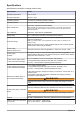
Specifications Specifications are subject to change without notice. Specification Details Operating temperature -5°C to +40°C Storage temperature -20°C to +70°C Operating humidity 0 to 95% non condensing relative humidity Operating altitude From 0 to 2,000 m. (6,550 ft.) above sea level EMC requirements Note: The wall mount instrument is a Class A product. In a domestic environment this product may cause radio interference in which case the user may be required to take adequate measures.
Specification Details Panel mount instrument (housing) (H x D x W) 156 (123) x 250 x 220 (214) mm - weight 2.9 kg 6.14 (4.84) x 9.84 x 8.86 (8.43) ins. - weight 6.39 lbs Portable (H x D x W) 225 x 250 x 219 mm - weight 3.8 kg 8.86 x 9.84 x 8.62 ins. - weight 8.38 lbs General information In no event will the manufacturer be liable for direct, indirect, special, incidental or consequential damages resulting from any defect or omission in this manual.
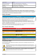
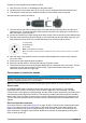
This symbol, when noted on the product, indicates that the marked item can be hot and should not be touched without care. This symbol, when noted on the product, indicates the presence of devices sensitive to electrostatic discharge and indicates that care must be taken to prevent damage to them. This symbol, when noted on the product, identifies the location of the connection for protective earth (ground).
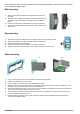
instrument on the floor. The instrument provides two folded legs hidden in the lower frame. Pull them out to modify the display angle. Wall mounting 1. Attach the U-bracket (provided) to the wall with two screws (not provided). 2. Tilt the instrument slightly backwards to align the bracket pins and the insertion slots, and slide the instrument onto the bracket as shown. 3. Insert the 2 locking screws with washers through the side slots. 4.
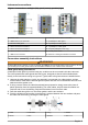
Instrument connections Figure 1 Connections - wall/pipe (left); panel (center); portable (right) 1 Power cable 8 External pressure sensor connection 2 USB-B client 4-pin connector 9 Input/Output 3 cable gland 3 Ethernet cable gland 10 Input/Output 2 cable gland 4 Sensor channel 3 connection 11 Input/Output 1 cable gland 5 Sensor channel 2 connection 12 Keylock (wall/pipe mount only) 6 Sensor channel 1 connection 13 On/Off power switch 7 USB-A host connector 14 Ethernet - Harting RJ Industrial
NOTICE It is vitally important to ensure the shielding is pinched and secured between the two washers to ensure the shielding attaches directly to the instrument housing as a ground. Failure to do this could cause damage to the instrument, and for sensor cables give incorrect readings. 5. Reattach and tighten the cable gland nut. 6. Attach the wires to the corresponding terminal block connections.
Prepare the user-supplied power cable as follows: 1. Strip off 23 mm (0.9 ins.) of shielding from the power cable. 2. Cut back the live and neutral wires to 15 mm (0.6 ins.) in length but leave the earth wire as is. 3. Then strip off a small amount of external insulation from the three wires as required. Wire the female connector as follows: 1. Take the narrow end of the connector (4) in one hand and the main body (2) in the other and unscrew the two.
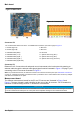
Main board Figure 3 Main board Figure 4 Connector P8 Connector P8 The numbers listed below refer to the 13 available P8 connections (from left to right) in Figure 4. 1. RS-485 (signal A) 8. Not used 2. RS-485 (signal B) 9. Not used 3. PROFIBUS-DP (GND) 10. Not used 4. PROFIBUS-DP (+ 5 V) 11. System alarm relay (N.O.) 5. PROFIBUS-DP (signal -) 12. System alarm relay (N.C.) 6. PROFIBUS-DP (signal +) 13. System alarm relay (Common) 7. PROFIBUS-DP (signal RTS) Connector P3 Ethernet RJ 45.
Figure 5 EC measurement board Figure 6 TC measurement board Figure 7 Connector J7 Figure 8 Connector J8 Connector J7 (inputs & outputs) The numbers listed below refer to the 16 available J7 connections (from left to right) in Figure 7. Measurement alarms relays: Analog current (or voltage) outputs: 1. Common 5. GND 2. Output relay 1 6. Output 1 3. Output relay 2 7. Output 2 4. Output relay 3 8. Output 3 Digital inputs: 9. EC sensor: Not used 10. Not used 9.
Connector J8 (sensor) The numbers listed below refer to the 10 available J8 connections (from left to right) in Figure 8. The colors indicated are the wire colors in the sensor cable. Note: Remember, this connector is colored orange for EC sensors and black for TC sensors. A1100 EC sensor 31xxx EC sensor 31xxxS smart EC sensor TC sensor Sensor cable wall or panel LEMO 10 cable portable 1. Guard electrode Guard electrode Guard electrode GND for power Yellow Brown 2.
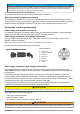
In addition, and to prevent any damage to the sensor electronics, the use of a purge safety backup unit (ORBISPHERE Model 32605) is highly recommended to ensure the supply of purge gas remains uninterrupted to the sensor in the event of a mains power outage. The above ORBISPHERE accessories are explained in more detail in the TC Sensor Installation and Maintenance manual. User interface Instrument controls The instrument front panel provides: • A touch screen acting as display, touch pad and keyboard.
Option Description User action logging When enabled every action from a logged on user is recorded in a user log file. User action log file The log file is a rolling buffer recording recent actions. Press Clear to empty the log file. User management Select Access table from the Security menu to show the list of registered users (a maximum of 99 users allowed). They are listed by name, ID, password and access level. Pressing on an empty line or the Add button displays a window to add a new user.
Option Description Pressure Select the barometric pressure units. Temperature Select the temperature units. Sample mode measurements (portable instrument) 1. Press the start/stop function key (on the header bar) to initiate the sample measurement. The text In progress and the measurement value are displayed sequentially. The measurement process stops when the stop criteria selected are fulfilled. 2.
Option Description Max. time The parameter Max. time is the maximum time allowed to reach the target. If Time is not the type of stop criteria, then when this delay has elapsed, the measurement stops and the message aborted is displayed. Time filter The time filter allows you to filter the stop criteria. The sample mode is stopped when the stop criteria is fulfilled for a time greater than the parameter Time Filter. As an example, if criteria is set to Above threshold and Time Filter is set to 10 sec.
Option Description Hysteresis The hysteresis is used to prevent relay flickering when the measurement is just at the alarm levels. Set this to a minimum but enough to eliminate flickering. For example, if the High Alarm is set to 40 ppb and the Hysteresis is set to 10% then the High Alarm is activated once the measurement reaches 40 ppb but only deactivated once it drops below 36 ppb.
Option Description Enable negative concentration Check as appropriate. Continuous purge during thermal cut off If thermal cutoff has been enabled (see Measurement configuration on page 16), then check this box to ensure that a continuous purge of the TC sensor takes place while the measurement session is suspended due to the thermal cutoff temperature value being exceeded.
Note: The temperature sensor is factory calibrated and can only be changed by a Hach Lange representative. Definitions To calibrate the gas to measure (main gas), the user usually puts the sensor in the main gas without any interfering gas. Calibrations can only be performed once the instrument has been installed, configured and each channel has been set up. You must also ensure that you have the correct access rights to access the calibration menu.
• The display shows the actual calibration parameters, and the actual readings (temperature, barometer, current). O2 sensor calibration The O2 sensor needs to be calibrated after each sensor service. Wait at least 30 minutes after mounting a new membrane before re-calibrating. The sensor is in contact with either: • Air at atmospheric pressure (In Air) • O2 at known concentration (Direct value). The gas can be dissolved or not.
Membrane Recommended calibration gas 2995A 100% H2 29015A 100% H2 TC gas sensor calibration Calibration of the measured gas 1. Before initiating a calibration process, the calibration parameters must be set by pressing on the Modify button. The last calibration parameters are memorized, so this step can be ignored if the correct parameters are already set. Similarly, if only the calibration value has changed, then this can be updated directly instead of pressing the Modify button.
External pressure calibration (optional sensor) Two point calibration (recommended) 1. Connect a certified absolute pressure gauge to the sample line, and use a certified precision barometer. 2. The two point calibration starts with barometric pressure for the lower point. Expose the external pressure sensor to the atmosphere. 3. Enter the barometric pressure read on the barometer in the upper window and validate P1. 4.
Maintenance Instrument maintenance CAUTION Personal Injury Hazard. Any instrument maintenance should be carried out by a qualified Hach Lange Service Technician. Please contact your local representative should you feel any maintenance or instrument adjustments are required.
Spezifikationen Die Spezifikationen können ohne Vorankündigung Änderungen unterliegen. Spezifikation Details Betriebstemperatur -5°C bis +40°C Lagerungstemperatur -20°C bis +70°C Betriebsfeuchtigkeit 0 bis 95% relative Feuchtigkeit ohne Kondensbildung Betriebshöhe Von 0 bis 2.000 m über dem Meeresspiegel EMC-Anforderungen Hinweis: Das Instrument für die Wandmontage ist ein Produkt der Klasse A.
Spezifikation Details Instrument für Paneelmontage (Gehäuse) (H x T x B) 156 (123) x 250 x 220 (214) mm - Gewicht 2,9 kg 6,14 (4,84) x 9,84 x 8,86 (8,43) ins. - Gewicht 6,39 lbs tragbar (H x T x B) 225 x 250 x 219 mm - Gewicht 3,8 kg 8.86 x 9.84 x 8.62 ins. - Gewicht 8,38 lbs Allgemeine Informationen Der Hersteller ist nicht verantwortlich für direkte, indirekte, versehentliche oder Folgeschäden, die aus Fehlern oder Unterlassungen in diesem Handbuch entstanden.
Aufkleber mit Vorsichtshinweisen Bitte lesen Sie alle auf dem Produkt angebrachten Etiketten und Hinweise. Die Nichtbeachtung kann zu Verletzungen an Personen oder einer Beschädigung des Produkts führen. Dieses Symbol auf einem Produkt zeigt eine potenzielle Gefahr an, die zu ernsthaften Verletzungen und/oder zum Tod führen kann. Der Benutzer soll dieses Handbuch bei der Bedienung des Geräts und/oder für Sicherheitsinformationen verwenden.
VORSICHT Verletzungsgefahr. Nur qualifiziertes Personal sollte die in diesem Kapitel des Handbuchs beschriebenen Aufgaben durchführen. HINWEIS Installieren Sie das Gerät an einem Standort und in einer Position, wo es zur Bedienung und zum Abschalten/Abklemmen gut zugänglich ist. HINWEIS Möglicher Geräteschaden Empfindliche interne elektronische Bauteile können durch statische Elektrizität beschädigt werden, wobei dann das Gerät mit verminderter Leistung funktioniert oder schließlich ganz ausfällt.
Paneelmontage 1-3 4-5 6-7 1. 2. 3. 4. Schneiden Sie eine Öffnung in den mitgelieferten. Installieren Sie den mitgelieferten Rahmen in der Öffnung. Falten Sie die 6 Zapfen mit einer Zange über die Lippen des Paneels. Schieben Sie das Instrument in den Bügelrahmen. Das Instrument sollte über die 4 "T"-Stifte gehen. Drehen Sie die 4 Befestigungsschrauben auf beiden Seiten des Frontpaneels und schieben Sie es hinein. 5.
Anweisungen zur Montage der Steckverbindungen WARNUNG Potenzielle Stromschlaggefahr. Um die NEMA/IP-Umweltbedingungen des Gehäuses zu wahren, benutzen Sie zur Verlegung von Kabeln im Geräteinnern nur Rohranschlussstücke und Kabeldurchführungen, die mindestens NEMA 4X/IP65 erfüllen. Anweisungen zur Verkabelung des Kabeldurchlasses Jedes Mal, wenn ein Kabel im Inneren des Instruments angeschlossen werden muss, wird ein wasserdichter Kabeldurchlass mitgeliefert.
Anschluss der Stromversorgung (Niederspannungsinstrumente) Bei den Niederspannungsinstrumenten (10-30 Vdc) der Stromversorgung erfolgt der Anschluss über einen BINDER-Stecker mit 7 Kontaktstiften (mitgeliefert). Hinweis: Die Steckverbindungen weisen Kehlen auf, um ein falsches Einstecken in das Instrument zu verhindern. Schließen Sie das Stromkabel wie folgt an die Steckverbindung an: Abbildung 2 Steckverbindung BINDER Kontaktstifte: 1. 2. 3. 4. 5. 6. 7.
1. Nehmen Sie das schmale Ende der Steckverbindung (4) in eine Hand und den Hauptkörper (2) in die anderen und schrauben Sie sie auseinander. Ziehen Sie die Kabelklemme (3) ab und schrauben Sie das Steckerende (1) ab, um zu den vier teilen gelangen, aus denen die Steckverbindung besteht. 2. Lösen Sie die Schrauben der Kabelklemme (3), so dass das Stromkabel hindurchgeführt werden kann. 3.
Mainboard Abbildung 3 Mainboard Abbildung 4 Steckverbindung P8 Steckverbindung P8 Die unten aufgeführten Zahlen beziehen sich auf die 13 verfügbaren Steckverbindungen P8 (von rechts nach links) in Abbildung 4. 1. RS-485 (Signal A) 8. Nicht verwendet 2. RS-485 (Signal B) 9. Nicht verwendet 3. PROFIBUS-DP (GND) 10. Nicht verwendet 4. PROFIBUS-DP (+ 5 V) 11. Systemalarmrelais (N.O.) 5. PROFIBUS-DP (Signal -) 12. Systemalarmrelais (N.C.) 6. PROFIBUS-DP (signal +) 13. Systemalarmrelais (gemein) 7.
Abbildung 5 EC-Messkarte Abbildung 6 TC-Messkarte Abbildung 7 Steckverbindung J7 Abbildung 8 Steckverbindung J8 Steckverbindung J7 (Eingänge und Ausgänge) Die unten aufgeführten Zahlen beziehen sich auf die 16 verfügbaren Steckverbindungen J7 (von rechts nach links) in Abbildung 7. Messungsalarmrelais: Analoge Strom- (oder Spannungs-) Ausgänge: 1. Gemein GND 2. Ausgangsrelais 1 6. Ausgänge 1 3. Ausgangsrelais 2 7. Ausgang 2 4. Ausgangsrelais 3 8. Ausgang 3 Digitale Eingänge: 9.
Steckverbindung J8 (Sensor) Die unten aufgeführten Zahlen beziehen sich auf die 10 verfügbaren Steckverbindungen J8 (von rechts nach links) in Abbildung 8. Die Farben geben die Farben der Drähte des Sensorkabels an. Hinweis: Bednken Sie, dass diese Steckverbindung für EC-Sensoren orange und für TC-Sensoren schwarz ist. EC-Sensor A1100 EC-Sensor 31xxx Smart EC-Sensor 31xxxS TC-Sensor Kabel des Sensors Wandbzw. Paneel LEMO 10-Kabel tragbare 1.
Zur Gewährleistung der Zufuhr von Gas während des Kontakts des Sensors mit der Probe empfehlen wir dringend den Einsatz eines Reserve-Gaszylinders mit einem automatischen Umschaltventil, das aktiviert wird, wenn der erste Zylinder leer ist. Außerdem empfehlen wir den Einsatz des Gasreglers Orbisphere Modell 29089 (oder eines vergleichbaren Reglers), um sicherzustellen, dass der Sensor ständig mit auf 40 µm gefiltertem Reinigungsgas mit dem richtigen Druck versorgt wird.
Sicherheit konfigurieren Definieren Sie Zugangsniveau für alle Benutzer. Dazu ist ein Benutzer mit der Zugangsebene 4 erforderlich. 1. Wählen Sie Konfiguration aus dem Menü Sicherheit. Option Beschreibung Zugangsrechte Wenn aktiviert nur registrierte Benutzer können die Menüs zuzugreifen. Wenn diese Option deaktiviert ist (Standard), sind alle Menüs frei zugänglich und in der Protokolldatei wird bei keinem Vorgang ein Name registriert werden. Max.
Menü Messung Konfigurierung des Instruments Berechnung der TPO oder TPA einer Einheit (tragbares Instrument) Die TPO-Funktion und die TPA-Funktion ist auf dem tragbaren Instrument für einen EC-Sensor zur Sauerstoffmessung verfügbar. Um diese Option erstmals zu verwenden, muss das Instrument in der Modalität Probe konfiguriert und die TPO oder TPA-Berechnung aktiviert werden.
Konfigurierung der Kriteriums Anhalten (tragbares Instrument) Diese Einstellung ist in der Modalität Messung Probe und gestattet die Konfigurierung des Kriteriums Anhalten für den einzelnen Kanal. Hinweis: Die verfügbaren Parameter hängen vom dem definierten Typ des Kriterium Anhalten ab. 1. Wählen Sie Menü / Haupt / Kanal x konfigurieren und drücken Sie die Taste Kriterium Anhalten.
Option Beschreibung Auflösung der Anzeige: Die maximale Auflösung ist vom Gas, von der Membran und der Einheit abhängig. Es können maximal 5 Stellen angezeigt werden. Für eine einfachere Ablesungen können die Dezimalstellen auf 0, 1, 2 oder 3 begrenzt werden. Dies hat keine Auswirkung auf die tatsächliche Auflösung des gemessenen und abgespeicherten Werts, sondern nur auf den angezeigten Wert.
1. Drücken Sie auf dem Bildschirm Messkonfiguration die Schaltfläche Filter. Option Beschreibung Status Stellen Sie der Messungsfilter Aktiviert oder Deaktiviert. Typ Falls aktiviert stellen Sie der filter Durchschnitt oder Median. Durchschnitt ist der Mathematischer Durchschnitt des letzten Messungsdatensatzes (Tiefe). Median gestattet die Beseitigung atypischer Spitzen der Messwerte und bildet den Durchschnitt der verbleibenden.
Option Beschreibung Faktor Flüssigkeit zu Gas Befähigen Sie die Korrektur auf geeignete Weise. Falls befähigt, muss der prozentuale Korrekturfaktor eingegeben werden. Dieser Wert kann nicht negativ sein. Hinweis: Bitte wenden Sie sich zuerst an den Kundendienst von Hach Lange, falls Sie glauben, dass Sie diese Korrekturen anwenden müssen. Konfiguration der Interferenz Diese Option ist verfügbar, um den Einfluss einiger Komponenten oder Gase auf die Probe während der Messung zu berücksichtigen.
Die Kalibrierung kann nur vorgenommen werden, nachdem das Instrument installiert und konfiguriert und alle Kanäle eingerichtet worden sind. Sie müssen außerdem sicherstellen, dass Sie über die richtigen Zugangsrechte für den Zugang zum Menü Kalibrierung verfügen. Wählen Sie Sensorkalibrierung im Kalibrierungsmenü und wählen Sie dann den zu kalibrierenden Kanal aus. In Abhängigkeit vom zu messenden Gas und vom Typ des verwendeten Sensors stehen zwei Typen der Gassensorkalibrierung zur Verfügung: 1.
• Der Wert “% Variation” zeigt die Variation während der letzten drei Messungen an, das bedeutet die Stabiltät der Messungen. Für eine präzise Kalibrierung ist eine möglichst geringe Variation erforderlich. • Die Anzeige zeigt die Parameter der aktuellen Kalibrierung und die aktuellen Messungen (Temperatur, barometr, Strom) an. O2 -Sensor kalibrieren Der O2 -Sensor muss nach jeder Wartung des Sensors kalibriert werden.
Membran Empfohlenes Kalibrierungsgas 2956A 1% H2 / 99% N2 2952A 10% H2 / 90% N2 2995A 100% H2 29015A 100% H2 Kalibrierung des TC-Gassensors Kalibrierung des gemessenen Gases 1. Vor der Initialisierung des Kalibrierungsprozesses müssen die Kalibrierungsparameter durch Drücken der Taste Änder eingegeben werden. Die Parameter der letzen Kalibrierung sind abgespeichert, so dass dieser Schritt ignoriert werden kann, falls die richtigen Parameter bereits eingestellt sind.
Kalibrierung des barometrischen Drucks Hinweis: Der barometrische Sensor wurde im Werk kalibriert, er sollte jedoch periodisch mit einem zertifizierten Präzisionsbarometer verifiziert werden. Dies ist nur erforderlich bei der Messung in Gasphasen mit Fraktionseinheiten (%, ppm). Das obere Feld zeigt den barometrischen Druck an, der vom Instrument gemessen wird. Messen Sie den barometrischen Druck an der Stelle, an der das Messinstrument verwendet wird, mit einem zertifizierten Präzisionsbarometer.
Sprachauswahl Wählen Sie die gewünschte Sprache ein und starten Sie das Instrument erneut, um die Änderung auszuführen. Uhr Aktualisieren Sie Zeit und Datum. Sonstige Menüs Für Informationen bezüglich der Einstellung für die Relais und den analogen Ausgang beziehen Sie sich bitte auf das vollständige Handbuch (Menü Eingänge/Ausgänge).
Specifiche Le specifiche sono soggette a modifica senza preavviso. Specifiche Dettagli Temperatura operativa Da -5°C a +40°C Temperatura di stoccaggio Da -20°C a +70°C Umidità d'esercizio Da 0 a 95% di umidità relativa senza condensa Altitudine di esercizio Da 0 a 2.000 m. (6.550 piedi) sopra il livello del mare Requisiti EMC Nota: Lo strumento montato a parete è un prodotto di Classe A.
Specifiche Dettagli Strumento con montaggio a parete e su tubo (A x P x L) 236,5 x 160 x 250 mm - peso 3,8 kg 9,31 x 6,30 x 9,84 ins. - peso 8,38 lbs Strumento con montaggio a pannello (alloggiamento) (A x P x L) 156 (123) x 250 x 220 (214) mm - peso 2,9 kg 6,14 (4,84) x 9,84 x 8,86 (8,43) ins. - peso 6,39 lbs Portatile (A x P x L) 225 x 250 x 219 mm - peso 3,8 kg 8.86 x 9.84 x 8.62 ins.
Etichette precauzionali Leggere tutte le etichette e le targhette applicate sul prodotto. La mancata osservanza delle precauzioni segnalate potrebbe causare lesioni personali o danni al prodotto. Questo simbolo, se presente sul prodotto, indica un potenziale pericolo che potrebbe causare gravi lesioni personali e/o morte. Per le istruzioni sul funzionamento dello strumento e/o le informazioni inerenti alla sicurezza, l'utente deve attenersi a quanto riportato nel presente manuale.
ATTENZIONE Pericolo di lesioni personali. Le operazioni riportate in questa sezione del manuale devono essere eseguite esclusivamente da personale qualificato. AVVISO Installare il dispositivo in un luogo e in una posizione che fornisce facile accesso per la disconnessione e il funzionamento del dispositivo. AVVISO Danno potenziale allo strumento. Componenti elettronici interni delicati possono essere danneggiati dall'elettricità statica, compromettendo le prestazioni o provocando guasti.
1. 2. 3. 4. Creare un'apertura nel pannello per inserire l'intelaiatura della staffa fornita in dotazione. Installare l'intelaiatura fornita in dotazione nell'apertura. Piegare le 6 alette lungo i bordi del pannello, utilizzando delle pinze regolabili. Fare scorrere lo strumento nell'intelaiatura della staffa. Lo strumento deve posizionarsi sopra i quattro perni a “T”. Ruotare le quattro viti di fissaggio su entrambi i lati del pannello anteriore e farlo scorrere all'interno. 5.
3. Fare passare il cavo attraverso il dado, la guarnizione in gomma e le due rondelle. 4. Serrare la schermatura in modo da comprimerla tra le due rondelle e far passare il cavo nella copertura, bloccando il pressacavo. 1 Cavo 3 Strumento 5 Anello di tenuta 7 Guarnizone 2 Schermatura 4 Filo 6 Rondelle 8 Dado di compressione AVVISO È importante che la schermatura sia bloccata tra le due rondelle per garantirne il contatto con la copertura dello strumento, così da assicurarne la messa a terra.
collegare il connettore femmina direttamente al connettore di alimentazione dello strumento. I due connettori sono scanalati per evitare errori di collegamento. Fissare saldamente il connettore femmina al connettore di alimentazione dello strumento. Qualora nessun cavo di alimentazione sia stato ordinato insieme allo strumento, sarà necessario collegare una spina di alimentazione al connettore femmina fornito in dotazione, come descritto nella seguente procedura. ATTENZIONE Pericolo di lesioni personali.
Collegamento ai pannelli elettrici AVVISO Danno potenziale allo strumento. Componenti elettronici interni delicati possono essere danneggiati dall'elettricità statica, compromettendo le prestazioni o provocando guasti. Nota: Tutti i cavi di collegamento devono essere legati insieme con appositi nastri di nylon. Cavo sensore Un cavo ORBISPHERE è necessario per collegare il/i sensore/i allo strumento. Gli strumenti portatili dispongono di un connettore Lemo 10 per la connessione del cavo sensore.
Ethernet RJ 45. Collegare gli strumenti a parete e a pannello alla rete locale facendo passare un cavo ethernet nell'apposito pressacavo (posizione pressacavo illustrata nella Figura 1 a pagina 51) e collegando il connettore P3 come illustrata nella Figura 3. Nota: Per gli strumenti portatili, il collegamento ethernet è localizzato sul pannello posteriore (vedere Connessioni dello strumento a pagina 51).
Ingressi digitali: 9. Sensore EC: Non utilizzato 9. Sensore TC: Ingresso in standby (cortocircuito sul pin 12) 10. Non utilizzato Ingressi analogici (quando il sensore pressione esterna è collegato direttamente) Ingressi analogici (quando il sensore pressione esterna N° di serie 32548.xx) 12. Sensore EC: Non utilizzato 12. Sensore EC: Non utilizzato 12. Sensore TC: GND 12. Sensore TC: GND 13. Verde: ingresso pressione esterna est. P+ 13. Verde: ingresso pressione esterna est. P+ 14.
Relè allarme misurazione I tre relè di uscita sono collocati sulla scheda di misurazione. È possibile configurare i relè singolarmente su Normalmente aperto (NO) o Normalmente chiuso (NC) spostando fisicamente il jumper su ciascun relè.
Navigazione del menu Premendo il pulsante “menu” presente sulla barra di intestazione è possibile richiamare il menu principale. Il display è suddiviso in tre colonne: • La colonna di sinistra mostra i menu o i sottomenu • La colonna centrale mostra una vista ad albero della posizione attuale all'interno della struttura del menu • La colonna di destra contiene i seguenti comandi generici: • • • • Indietro - Ritorna al menu precedente (arretrando di un livello) Princip.
Menu vista Vista numerica Modalità di visualizzazione predefinita che mostra il valore di misurazione numerico per ciascun canale di misurazione gas disponibile, un grafico indicante l'evoluzione dei valori rilevati all'interno di un determinato lasso di tempo e la temperatura del campione. Il display si aggiorna dopo ogni ciclo di misurazione che può essere configurato a seconda delle esigenze dell'utente. Selezionare Configura dal menu Vista seguito da Config.
• È stato premuto il tasto funzione avvio/stop • Il criterio Tempo massimo è stato raggiunto • Si è verificato un errore avvenuto un errore (ad es. sensore assente) 3. Quando la misurazione del campione si arresta a causa del raggiungimento dei criteri di blocco, la concentrazione di gas e la temperatura non vengono più aggiornate. Essi indicano il valore misurato nel momento in cui sono stati raggiunti i criteri di blocco.
Opzione Descrizione Media Fase liquida o gassosa. Tipo unità gas Parziale, Frazionata, Disciolta. Unità gas La lista delle unità disponibili dipende dal tipo di unità selezionato. Nota: E’ la concentrazione di gas misurata dal sensore EC. Quando viene selezionata un’unità composita, (ad es. ppm » ppb) l’unità cambia a seconda della portata del valore da visualizzare. Liquido Quando il mezzo è liquido, selezionare acqua o altro liquido con differente solubilità (se disponibile).
Opzione Descrizione Isteresi L'isteresi è utilizzata per evitare lo sfarfallio del relè quanto la misurazione è vicina al livello di allarme. Impostare un valore minimo ma comunque sufficiente ad eliminare lo sfarfallio. A titolo di esempio, se il livello di allarme Alto è impostato a 40 ppb e l'Isteresi è del 10%, l'Allarme Alto si attiva quando la misurazione raggiunge 40 ppb, ma si disattiva solo quando la misurazione scende al di sotto delle 36 ppb.
Opzione Descrizione Calcolo del TPA attivo (strumenti portatili configurati solo in Modalità campione) Selezionare quest'opzione se si desidera eseguire il calcolo del TPA. Coefficiente K TPA Quando la funzione TPA è abilitata, impostare il coefficiente K TPA se diverso dal valore visualizzato. 2. Sensore TC Opzione Descrizione Abilita sensore di press. est Selezionare se necessario. Abilita concentrazione negativa Selezionare se necessario.
Opzione Descrizione Memorizza una volta Quando la memoria temporanea è satura (10.000 valori), la registrazione delle misure si arresta. Memoria ciclica Quando la memoria temporanea è satura, l'ultima serie di misure sostituisce quella più datata (metodo first-in, first-out). 2.
Opzione Descrizione Liquido Selezionare la voce appropriata, disponibile solo quando liquido è stato selezionato in Media (vedi sopra). Valore Inserire la concentrazione di gas in base al valore della media di taratura, quando viene utilizzato valore diretto. Sospendi durante calibrazione Selezionata per default, questa funzione blocca l'emissione di dati dallo strumento durante il processo di taratura, per evitare l’invio di informazioni errate ad altre strumentazioni collegate.
Impostare gli opportuni parametri di taratura e premere OK. Taratura del sensore di O3 Il sensore è a contatto con uno dei seguenti elementi: • Aria a pressione atmosferica (In Aria) • Concentrazione nota di O3 (Valore diretto). Il gas può essere disciolto oppure no. La procedura è identica a quella del sensore di O2. In caso di taratura “In aria”, il sensore misura la quantità di O2 durante la taratura. Il coefficiente di O3 viene dedotto in base al comportamento del sensore in presenza di O2.
Opzione Descrizione Interruzione automatica calibrazione Interruzione automatica calibrazione: Se attivata, questa funzione consente di interrompere automaticamente il processo di calibrazione quando vengono raggiunti i criteri di stabilità. Interferenze attivate Se selezionata, questa opzione considera l’influenza delle interferenze in fase di calibrazione. L’impostazione di default prevede l’opzione stesse interferenze durante misurazione. 2.
Calibrazione su un punto 1. Collegare un indicatore di pressione assoluta certificato alla linea del campione. 2. Esporre il sensore della pressione esterna alla linea di pressione, assicurandovi che sia esposto alla stessa pressione dell’indicatore di pressione assoluta. 3. Inserire il valore di pressione assoluta che si legge dall’indicatore nella casella sottostante e premere il tasto convalida P1.
Spécifications Les spécifications peuvent faire l’objet de modifications sans préavis. Spécification Détails Température de fonctionnement -5°C à +40°C Température de stockage -20°C à +70°C Humidité de fonctionnement 0 à 95 % humidité relative sans condensation Altitude de fonctionnement De 0 à 2 000 m. (6 550 pieds) au-dessus du niveau de la mer Exigences EMC Remarque : L'instrument pour montage mural est un produit de Classe A.
Spécification Détails Instrument pour montage sur mural/sur tuyau (H x P x L) 236.5 x 160 x 250 mm - poids 3.8 kg 9.31 x 6.30 x 9.84 ins. - poids 8.38 lbs Instrument pour montage sur panneau (boîtier) (H x P x L) 156 (123) x 250 x 220 (214) mm - poids 2.9 kg 6.14 (4.84) x 9.84 x 8.86 (8.43) ins. - poids 6.39 lbs Portable (H x P x L) 225 x 250 x 219 mm - poids 3.8 kg 8.86 x 9.84 x 8.62 ins. - poids 8.
Étiquettes de mise en garde Lisez toutes les étiquettes fixées au produit. Dans le cas contraire, des blessures ou des dégâts au produit peuvent se produire. Lorsqu'il est apposé sur un produit, ce symbole indique un risque potentiel qui pourrait provoquer des dommages corporels graves et/ou la mort. L'utilisateur doit se référer à ce manuel d'instructions pour l'utilisation et/ou les informations de sécurité.
ATTENTION Risque de blessures corporelles. Seul le personnel qualifié peut effectuer les tâches décrites dans cette section du manuel. AVIS Installez l'appareil à un emplacement et dans une position qui ne gênent pas son fonctionnement et permettent d'accéder facilement à l'interrupteur externe. AVIS Dégât potentiel sur l'appareil Les composants électroniques internes de l'appareil peuvent être endommagés par l'électricité statique, qui risque d'altérer ses performances et son fonctionnement.
1. 2. 3. 4. Découpez une ouverture dans le panneau pour recevoir le cadre support fourni. Installez le cadre fourni dans l'ouverture. Pliez les 6 languettes par-dessus les bords du panneau, à l'aide d'une pince multiprise. Glissez l'instrument dans le cadre support. L'instrument doit venir sur les quatre ergots en « T ». Faites tourner les 4 vis blocage rapide sur les deux côtés de la face avant et faites-le glisser à l'intérieur. 5.
3. Passez le câble à travers l'écrou, le joint et les deux rondelles. 4. Pincer le blindage afin que la totalité de sa circonférence soit pressée entre les deux rondelles et passez le câble dans le boîtier en bloquant le passe-câble.
Si ce connecteur femelle a été fourni avec une fiche d'alimentation déjà raccordée (câble numéros de pièce 33031, 33032, 33033 et 33034), le connecteur femelle peut être branché directement dans le connecteur d'alimentation de l'instrument. Les deux connecteurs possèdent un détrompeur pour éviter un raccordement incorrect. Serrez le connecteur femelle sur le connecteur d'alimentation de l'instrument avec les doigts.
raccordement incorrect. Serrez le connecteur femelle sur le connecteur d'alimentation de l'instrument avec les doigts. Connexions aux cartes électroniques AVIS Dégât potentiel sur l'appareil Les composants électroniques internes de l'appareil peuvent être endommagés par l'électricité statique, qui risque d'altérer ses performances et son fonctionnement. Remarque : Tous les conducteurs libres doivent être rassemblés en faisceau en utilisant des attaches nylon pour câbles.
Les numéros indiqués ci-dessous se réfèrent aux 13 connexions P8 disponibles (de gauche à droite) dans Figure 4 1. RS-485 (signal A) 8. Non utilisé 2. RS-485 (signal B) 9. Non utilisé 3. PROFIBUS-DP (TERRE) 10. Non utilisé 4. PROFIBUS-DP (+ 5 V) 11. Relais d'alarme système (N.O.) 5. PROFIBUS-DP (signal -) 12. Relais d'alarme système (N.C.) 6. PROFIBUS-DP (signal +) 13. Relais d'alarme système (Commun) 7. PROFIBUS-DP (signal RTS) Connecteur P3 Ethernet RJ 45.
Connecteur J7 (entrées et sorties) Les numéros indiqués ci-dessous se réfèrent aux 16 connexions J7 disponibles (de gauche à droite) dans Figure 7 Relais d'alarme de mesure : Sorties courant analogique (ou tension) : 1. Commun TERRE 2. Relais de sortie 1 6. Sortie 1 3. Relais de sortie 2 7. Sortie 2 4. Relais de sortie 3 8. Sortie 3 Entrées numériques : 9. Capteur EC : Non utilisé 9. Capteur TC : Entrée attente (court-circuit à la broche 12) 10.
Relais d'alarme de mesure Les trois relais de sortie sont situés sur la carte de mesure. Ils peuvent être configurés individuellement sur « Normalement Ouvert » (NO) ou sur « Normalement fermé » (NC) en bougeant physiquement le pontage sur chaque relais.
Navigation par menus Le fait d'appuyer sur le bouton « menu » dans la barre d'en-tête appelle le menu principal.
Menu d'affichage Affichage numérique Il s'agit de l'affichage par défaut qui montre la valeur de mesure numérique identifiée pour chaque canal disponible de mesure de gaz, un graphique indiquant l'évolution de la valeur mesurée dans le cadre du temps préétabli et la température de l’échantillon. L'affichage est actualisé après chaque cycle de mesure qui peut être configuré pour s'adapter à des conditions particulières. Sélectionnez Configurer dans le menu Affichage suivi de Conf.
• Le Critère d'arrêt est satisfait, normalement lorsque la concentration en gaz atteint le seuil préétabli • La touche de fonction marche/arrêt a été enfoncée • Le critère de Durée maximale est atteint • Une erreur est survenue (ex. capteur retiré) 3. Lorsque la mesure d'échantillon s'arrête parce que les critères d'arrêt sont satisfaits, la concentration en gaz et la température ne sont plus rafraichies. Ils indiquent la mesure au moment où le critère d'arrêt a été atteint.
Configuration de mesure 1. Capteur EC Option Désignation Membrane Sélection du numéro de membrane du capteur. Support Phase liquide ou gazeuse. Type d'unité de gaz Partiel, fraction, dissous. Unité gaz La liste des unités disponibles dépend du type d'unité sélectionné ci-dessus. Remarque : Ceci est la concentration en gaz mesurée par le capteur gaz. Lorsqu'une unité composite est sélectionnée (ex. ppm » ppb) l'unité change en fonction de la plage de la valeur à afficher.
Option Désignation Hystérésis L'hystérésis est utilisée pour empêcher le relais de scintiller lorsque la mesure se situe juste aux niveaux d'alarme. Réglez celle-ci à un minimum mais suffisamment pour éliminer le scintillement. Par exemple, si l'alarme haute est établie à 40 ppb et que l'hystérésis est réglée à 10 %, l'alarme haute est alors activée une fois que la mesure atteint 40 ppb, mais seulement désactivée lorsque la mesure chute en dessous de 36 ppb.
Option Désignation Mesure de TPA active (instruments portables en mesure Mode échantillon uniquement) Cocher la case si le calcul TPA est nécessaire. Coefficient K de TPA Si TPA est activé, entre le coefficient K de TPA si différent de la valeur affichée 2. Capteur TC Option Désignation Activer le capteur de pression ext. Vérifier s'il y a lieu. Activer la concentration négative Vérifier s'il y a lieu.
Option Désignation Stocker une fois Lorsque la mémoire volatile est pleine (1 000 positions), l'enregistrement des mesures s'arrête. .Mémoire-tampon défilante lorsque la mémoire volatile est pleine, le dernier jeu de mesures remplace le plus ancien en continu (premier entré/ premier sorti). 2. Modes de stockage en mode de mesure d’échantillon: Option Désignation Mesure finale seulement Lorsque les critères d'arrêt sont atteints, la mesure est sauvegardée (une par échantillon).
Option Désignation Valeur Saisissez la concentration de gaz suivant la valeur dans le fluide d'étalonnage, lorsque la valeur directe est utilisée. En attente pendant l'étalonnage « On » par défaut, ceci arrête toute sortie de l'instrument pendant le processus d'étalonnage pour éviter d'envoyer des informations invalides vers tout dispositif connecté. Brouillage activé si sélectionné, ceci tient compte de l'influence des brouillages pendant l'étalonnage.
• Air à la pression atmosphérique (dans l'air), ou • O3 à une concentration connue (valeur directe). Le gaz peut être dissous ou non. La procédure est la même que pour le capteur O2. Dans le cas de l'étalonnage « Dans l'air », le capteur mesure O2 pendant l'étalonnage. Le coefficient O3 est déduit pour tenir compte du comportement du capteur dans l'O2. Comme une tension différente est utilisée à l'anode pour mesurer l'O2 et l'O3, la mesure de l'O3 prend beaucoup de temps pour se stabiliser.
Option Désignation Arrêt automatique de l'étalonnage si sélectionné, lorsque le critère de stabilité est atteint, l'opération d'étalonnage s'arrête automatiquement. Brouillage activé si sélectionné, ceci tient compte de l'influence des brouillages pendant l'étalonnage. Par défaut le même brouillage que pendant la mesure est sélectionné. 2. Appuyez sur OK pour démarrer l'étalonnage • Un écran d'étalonnage affiche les données des mesures en cours qui sont rafraîchies en continu.
Étalonnage un point 1. Branchez un manomètre absolu certifié sur la ligne d’échantillon. 2. Exposez le capteur de pression externe à la pression de la ligne, pour s'assurer qu'il est soumis à la même pression que le manomètre absolu certifié. 3. Saisissez la valeur de pression absolue lue sur le manomètre absolu certifié dans le champ du bas, et Validez P1.
Especificaciones Las especificaciones están sujetas a cambios sin previo aviso. Especificación Detalles Temperatura de funcionamiento De -5 °C a +40 °C Temperatura de almacenamiento De -20 °C a +70 °C Límites de humedad Humedad relativa sin condensación de 0 a 95% Altitud de funcionamiento De 0 a 2.000 m (6.550 pies) sobre el nivel del mar Requisitos EMC Nota: El instrumento de montaje en pared es un producto de clase A.
Especificación Detalles Opciones RS-485 o PROFIBUS-DP; Cliente USB; Host USB; Ethernet 10/100 Base-T Montaje en pared y en tubería (Alto x Profundo x Ancho) 236.5 x 160 x 250 mm - peso 3.8 kg 9.31 x 6.30 x 9.84 ins. - peso 8.38 lbs Montaje en panel (carcasa) (Alto x Profundo x Ancho) 156 (123) x 250 x 220 (214) mm - peso 2.9 kg 6.14 (4.84) x 9.84 x 8.86 (8.43) ins. - peso 6.39 lbs Portátil (Alto x Profundo x Ancho) 225 x 250 x 219 mm - peso 3.8 kg 8.86 x 9.84 x 8.62 ins. - peso 8.
Etiquetas de precaución Lea todas las etiquetas y marcas pegadas al producto. Se pueden producir lesiones personales o daños en el producto si no se tienen en cuenta. Este símbolo, cuando aparece en un producto, indica el peligro potencial de que se puedan ocasionar lesiones personales graves y/o la muerte. El usuario debe consultar este manual de instrucciones para obtener información sobre su funcionamiento y/o seguridad.
PRECAUCIÓN Peligro de lesión personal. Las tareas descritas en esta sección del manual solo deben ser realizadas por personal cualificado. AVISO Instale el dispositivo en un lugar y una posición que facilite el acceso al dispositivo de desconexión y su operación. AVISO Daño potencial al instrumento. Los delicados componentes electrónicos internos pueden sufrir daños debido a la electricidad estática, lo que acarrea una disminución del rendimiento del instrumento y posibles fallos.
Montaje en panel 1-3 4-5 6-7 1. 2. 3. 4. Realice un corte en el panel para colocar la estructura de abrazadera proporcionada. Instale la estructura proporcionada en la apertura. Pliegue las 6 lengüetas sobre los bordes del panel con unos alicates ajustables. Deslice el instrumento en la estructura de abrazadera. El instrumento debe quedar colocado sobre los cuatro pernos T. Gire los 4 tornillos de fijación que hay a ambos lados del panel frontal y deslícelo hacia dentro. 5.
Instrucciones de montaje de los conectores ADVERTENCIA Posible peligro de electrocución. Para mantener las clasificaciones ambientales NEMA/IP de la carcasa, utilice solo conexiones de conductos y prensacables que cumplan como mínimo con el estándar NEMA 4X/IP65 para introducir los cables en el instrumento. Instrucciones de cableado de los casquillos para paso de cables Se proporciona un casquillo resistente al agua para el paso de cable que permite conectar un cable al interior del instrumento.
Conexión a la alimentación eléctrica (instrumentos de baja tensión) En el caso de los instrumentos de baja tensión (10-30 V CD), la conexión a la fuente de alimentación se realiza con un conector BINDER de 7 patillas (proporcionado). Nota: Los conectores disponen de ranuras para evitar un acoplamiento incorrecto al instrumento. Conecte el cable de alimentación al conector como se describe a continuación: Conexiones de patillas: Figura 2 Conector BINDER 1. No usado 2. Alimentación de 10-30 V CD 3.
1. Tome el extremo estrecho del conector (4) con una mano y el cuerpo principal (2) con la otra mano y desenrosque ambos. Aparte la abrazadera del cable (3) y desenrosque el conector del terminal (1) para ver las cuatro piezas que componen el conector. 2. Suelte los tornillos de la abrazadera del cable (3) de modo que quede suficiente espacio para pasar el cable de alimentación. 3.
Placa principal Figura 3 Placa principal Figura 4 Conector P8 Conector P8 Los números indicados abajo hacen referencia a las 13 conexiones P8 disponibles (de izquierda a derecha) en Figura 4. 1. RS-485 (señal A) 8. No usado 2. RS-485 (señal B) 9. No usado 3. PROFIBUS-DP (GND, conexión a tierra) 10. No usado 4. PROFIBUS-DP (+ 5 V) 11. Relé de alarma del sistema (NO) 5. PROFIBUS-DP (señal -) 12. Relé de alarma del sistema (Nc) 6. PROFIBUS-DP (señal +) 13. Relé de alarma del sistema (común) 7.
Figura 5 Placa de medición EC Figura 6 Placa de medición TC Figura 7 Conector J7 Figura 8 Conector J8 Conector J7 (entradas y salidas) Los números indicados abajo hacen referencia a las 16 conexiones J7 disponibles (de izquierda a derecha) en Figura 7. Relés de alarmas de medición: Salidas de corriente (o tensión) analógicas: 1. Común GND (conexión a tierra) 2. Relé de salida 1 6. Salida 1 3. Relé de salida 2 7. Salida 2 4. Relé de salida 3 8. Salida 3 Entradas digitales: 9.
Conector J8 (sensor) Los números indicados abajo hacen referencia a las 10 conexiones J8 disponibles (de izquierda a derecha) en Figura 8. Los colores indicados se corresponden con los colores de los hilos del cable del sensor. Nota: Recuerde que este conector es de color naranja para los sensores EC y de color negro para los sensores TC. Sensor EC A1100 Sensor EC 31xxx Sensor inteligente EC 31xxxS Sensor TC Cable del sensor pared o panel Cable LEMO 10 portá til 1.
AVISO No coloque el sensor TC en una muestra de líquido hasta que se haya conectado una fuente constante de gas de purga seco, ya que el líquido puede condensarse en el interior de la cámara de medición y ocasionar daños en el chip del conductor térmico. Para garantizar la continuación del gas de purga mientras el sensor está en contacto con la muestra, se recomienda usar un cilindor de gas de purga de respaldo con una válvula de cambio automático que se active cuando se vacíe el primer cilindro.
Configuración de la seguridad Definir los usuarios y sus niveles de acceso. Esto requiere un nivel de acceso de usuario 4. 1. Seleccione Configuración en el menú Seguridad. Opción Descripción Derechos de acceso Si están habilitados, es necesario iniciar sesión como un usuario registrado para acceder a los menús. Cuando están deshabilitados, se permite el acceso a todos los menús y no se registrará ningún nombre para la acción en el archivo de registro. Máx.
paquete se agita durante aproximadamente 5 minutos antes de la medición y conocer el volumen total del paquete y el volumen total del contenido del paquete. Modo continuo o de la muestra (instrumento portátil) El modo continuo se usa normalmente para la medición de procesos, mientras que el modo de muestras se emplea para las mediciones de laboratorio de muestras de pequeño volumen, como botes, frascos, etc. El modo de medición es un parámetro que se define para todo el instrumento, no para cada canal.
1. Seleccione Menú / Principal / Config. canal x y presione el botón Criterios de detención. Opción Descripción Arriba del umbral Los criterios de detención se cumplen cuando la concentración de gas es superior al parámetro introducido en Umbral. Debajo umbral Los criterios de detención se cumplen cuando la concentración de gas es inferior al parámetro introducido en Umbral.
La configuración de medición de un sensor TC es igual que la de un sensor EC, aunque existe un criterio de selección adicional: • Gas de purga: En la lista desplegable, seleccione el gas de purga que se utiliza para el sensor TC. Configuración de alarmas de medición Permite ajustar los umbrales de los niveles alto y bajo de concentración, según la aplicación específica. 1.
Configuración avanzada 1. Sensor EC Opción Descripción Habil. sensor presión Active esta opción si procede. Habil. conc. negativa Active esta opción si procede.
Almacenamiento de datos medidos Hay un archivo de mediciones por canal que contiene los datos generados por el ciclo de medición. 1. Modos de almacenamiento en el modo de medición continuo: Opción Descripción Ninguno El almacenamiento está desactivado. Almacenar una vez Cuando la memoria volátil se llena (10.000 posiciones), se detiene el registro de las mediciones.
memorizan, por lo que este paso se puede omitir si ya se han configurado los parámetros correctos. Opción Modo de calibración Descripción • Valor directo: Cualquier gas • En aire (valor predeterminado): Para O2 u O3. Medio Seleccione líquido o gas (sólo calibración directa) Tipo de unid. [de concentración] Parcial, fracción o disuelto (disuelto es para solamente la calibración en un líquido). Unidad de concentración la lista de unidades disponible depende del tipo de unidad seleccionado arriba.
calibración. A continuación, vuelva a colocar el casquillo de protección de forma suelta sobre el sensor, sujetándola con algunas vueltas del collarín. Configure los parámetros de calibración según corresponda y presione Calibrar. Calibración directa Este procedimiento calibra el sensor de oxígeno frente a una muestra de líquido que contiene un nivel conocido de O2 disuelto que fluye por la línea de muestras.
Opción Descripción Tipo unidad de gas Parcial, fracción o disuelto (disuelto es para solamente la calibración en un líquido). Unidad de gas la lista de unidades disponible depende del tipo de unidad seleccionado arriba. Líquido selecciona la opción apropiada. Valor Introduzca la concentración de gas según el valor del medio de calibración. Retención en calibración opción activada de forma predeterminada.
4. Exponga el sensor de presión externo a la presión de línea, asegurándose de que está expuesto a la misma presión que el medidor de presión absoluta certificado. 5. En el cuadro inferior, introduzca el valor de presión absoluta del medidor de presión absoluta certificado y valide la presión P2. Nota: Se puede utilizar cualquier presión para P1 y P2 pero, para una calibración precisa, los valores de P1 y P2 deben ser diferentes si es posible. Calibración en un punto 1.
Mantenimiento Mantenimiento del instrumento PRECAUCIÓN Peligro de lesión personal. El mantenimiento de cualquier instrumento lo debe llevar a cabo un técnico de servicio cualificado de Hach Ultra. Póngase en contacto con un representante local en caso de que el instrumento deba someterse a un mantenimiento o a ajustes.
Especificações As especificações estão sujeitas a alteração sem aviso prévio. Especificação Detalhes Temperatura de operação -5°C a +40°C Temperatura de armazenamento -20°C a +70°C Umidade de operação 0 a 95% de umidade relativa de não condensamento Altitude operacional De 0 a 2.000 m. (6.550 pés) acima do nível do mar Requisitos EMC Observação: O instrumento de montagem da parede é um produto de Classe A.
Especificação Detalhes Instrumento de montagem de parede e tubulação (A x P x L) 236.5 x 160 x 250 mm - peso 3.8 kg 9.31 x 6.30 x 9.84 pol. - peso 8.38 lbs Instrumento com montagem em painel (revestimento) (A x P x L) 156 (123) x 250 x 220 (214) mm - peso 2.9 kg 6.14 (4.84) x 9.84 x 8.86 (8.43) pol. - peso 6.39 lbs Portátil (A x P x L) 225 x 250 x 219 mm - peso 3.8 kg 8.86 x 9.84 x 8.62 pol. - peso 8.
Etiquetas de precaução Leia todos as etiquetas e adesivos fixados no produto. Ferimento pessoal ou dano ao produto poderia ocorrer se não observados. Este símbolo, quando observado em um produto, indica um perigo potencial que poderia causar ferimentos pessoais graves e/ou morte. O usuário deverá usar como referência este manual de instrução para operação e/ou informações de segurança.
CUIDADO Perigo de ferimento pessoal. Somente pessoal qualificado deve realizar as tarefas descritas nesta seção do manual. AVISO Instale o dispositivo em local e posição que permitam o acesso fácil ao dispositivo de desconexão e sua operação. AVISO Dano potencial do instrumento. Componentes eletrônicos internos delicados podem ser danificados devido à eletricidade estática, podendo resultar em degradação do desempenho ou em uma eventual falha.
1. 2. 3. 4. Corte uma abertura no painel para acomodar a estrutura do suporte fornecida. Instale a estrutura fornecida na abertura. Dobre as 6 abas sobre a borda do painel, usando alicates articuladas. Deslize o instrumento na estrutura da abraçadeira. O instrumento deve cair sobre os quatro pinos em “T”. Gire os 4 parafusos de fixação em ambos os lados do painel frontal e deslize-o para dentro. 5. Gire os 4 parafusos de fixação 1/4 duas vezes no sentido da trava como indicado no lado do painel frontal.
isolamento externo conforme necessário e 25 mm de blindagem. Descasque os fios em torno de 8 mm a partir das suas extremidades. 3. Passe o cabo pela porca, pela junta de borracha e pelas duas arruelas. 4. Aperte a blindagem de modo que sua circunferência total está pressionada entre as duas arruelas e passe o cabo pela carcaça, bloqueando o prensa-cabos.
Conexão da fonte de alimentação (instrumentos de alta tensão) Instrumentos de alta tensão (100-240 VAC) possuem um conector macho com 4 pinos pré-cablado internamente com um conector BINDER macho preparado para a conexão alimentação elétrica. Um conector fêmea compatível é fornecido com o instrumento.
6. Assegure o cabo de alimentação parafusando o conector terminal (1) de volta no lugar. 7. O conector fêmea pode agora ser conectado diretamente no conector de alimentação do instrumento. Os dois conectores são providos de ranhuras para evitar uma montagem incorreta. Aperte com a mão o conector fêmea ao conector de alimentação do instrumento. Conexões das placas eletrônicas AVISO Dano potencial do instrumento.
Os números listados abaixo referem-se às 13 conexões P8 disponíveis (da esquerda para a direita) em Figura 4 1. RS-485 (sinal A) 8. Não utilizado 2. RS-485 (sinal B) 9. Não utilizado 3. PROFIBUS-DP (GND) 10. Não utilizado 4. PROFIBUS-DP (+ 5 V) 11. Relé de alarme do sistema (N.O.) 5. PROFIBUS-DP (sinal -) 12. Relé de alarme do sistema (N.C.) 6. PROFIBUS-DP (sinal +) 13. Relé de alarme do sistema (Comum) 7. PROFIBUS-DP (sinal RTS) Conector P3 Ethernet RJ 45.
Os números listados abaixo referem-se às 16 conexões J7 disponíveis (da esquerda para a direita) em Figura 7 Relés de alarmes de medição: Saídas da corrente analógica (ou tensão): 1. Comum 5. GND 2. Relé de saída 1 6. Saída 1 3. Relé de saída 2 7. Saída 2 4. Relé de saída 3 8. Saída 3 Entradas digitais: 9. Sensor EC: Não utilizado 9. Sensor TC: Segurar entrada (curto-circuito no pino 12) 10.
Relés de alarmes de medição Os três relés de saída estão localizados na placa de medição. Eles podem ser configurados individualmente para Normalmente abertos (NO) ou para Normalmente fechados (NC) movendo fisicamente o conector em cada relé.
Menu navegação Ao pressionar o botão “menu” na barra de título abre o menu principal. A tela é composta de três colunas: • A esquerda mostra as opções do menu • O centro mostra uma exibição de árvore da posição dentro da estrutura do menu. • A direita tem os seguintes controles genéricos: • • • • Para cima - Retorna voltar ao menu anterior (um passo para trás) Principal - Pula diretamente para o menu principal Fechar - Fecha o menu e volta para a tela de medição.
Menu Visualização Visualização numérica Esta é a visualização padrão e mostra o valor de medição numérica identificado para cada canal de medição de gás disponível, um gráfico mostrando evolução de valor de medição durante o intervalo de tempo definido e temperatura de amostra. A exibição é atualizada após cada ciclo de medição que pode ser configurado para se adequado aos requisitos do usuário. Selecione Configurar a partir do menu Visualização seguido por Conf. vista numérica para personalizar a exibição.
• Os critérios de parada são atendidos, normalmente, quando a concentração de gás alcança o limiar estabelecido • A chave de função iniciar/parar foi pressionada • Os critérios de tempo máximo são alcançados • Ocorreu um erro (por exemplo, sensor fora) 3. Quando a medição da amostra para por que os critérios de parada são atendidos, a concentração de gás e a temperatura não são mais atualizadas. Elas indicam a medição quando os critérios de parada forem alcançados.
Configuração da medição 1. Sensor EC Opção Descrição Membrana Seleção do número da membrana do sensor. Meio Fase líquida ou gasosa. Tipo de unidade de gás Parcial, Fração, Dissolvido. Unidade de gás A lista de unidades disponíveis dependem do tipo de unidade selecionada acima. Observação: Esta é a concentração de gás medida pelo sensor EC. Quando uma unidade composta (por exemplo, ppm » ppb) é selecionada, a unidade mudará dependendo do valor de intervalo que será exibido.
Opção Descrição Hysteresis O histerese é usado para evitar que o relé “flutue” quando a medição está apenas nos níveis do alarme. Configure a um valor mínimo, porém o suficiente para eliminar a flutuação. Por exemplo, se o High Alarm é configurado para 40 ppb e o Hysteresis é configurado para 10%, então o High Alarm é ativado uma vez que a medição alcança 40 ppb, mas somente desativará quando a medição cai abaixo de 36 ppb.
Opção Descrição Habilitar TPA (instrumento portátil apenas em medição de modo de amostra) Verifique se o cálculo TPA é necessário Coeficiente TPA K Se o TPA for habilitado, insira o coeficiente TPA K, se for diferente do valor exibido. 2. Sensor TC Opção Descrição Habilite o texto. sensor de pressão Verifique conforme seja apropriado. Habilitar concentração negativa Verifique conforme seja apropriado.
Opção Descrição Armazene uma vez Quando a memória volátil está cheia (10,000 posições), a gravação da medição para. Buffer de rolamento Quando memória está cheia, a última série de medições substitui a mais antiga continuamente (primeiro a entrar, primeiro a sair). 2. Modos de armazenamento no modo de medição de amostra: Opção Descrição Apenas medição final A medição quando os critérios de parada são atendidos é salva (uma por amostra).
Opção Descrição Líquido Selecione conforme apropriado, disponível quando líquido tiver sido selecionado em meio (acima). Valor Insira a concentração de gás de acordo com o valor na mídia de calibração, quando o valor direto for usado. Segurar durante a calibração E por padrão, isso para qualquer saída do instrumento durante o processo de calibração para evitar enviar informações inválidas para qualquer dispositivo conectado.
Calibração do sensor O3 O sensor está em contato com: • Ar em pressão atmosférica (Ar de entrada) • O3 em concentração conhecida (Valor direto). O gás pode ser dissolvido ou não. O procedimento é o mesmo que para o sensor de O2. No caso da calibração do "Ar de entrada", o sensor mede O2 durante a calibração. O coeficiente de O3 é deduzido levando em consideração como o sensor se comporta em O2.
Opção Descrição Parada automática de calibração Se estiver selecionado, quando os critérios de estabilidade forem alcançados, o processo de calibração para automaticamente. Interferência habilitada Se estiver selecionado, isso leva em consideração a influência de interferências durante a calibração. Por padrão, a mesma interferência que durante a medição é selecionada. 2.
Calibração de um ponto 1. Conecte um medidor de pressão absoluta certificado a uma linha de amostra. 2. Exponha o sensor de pressão externa à pressão da linha, certificando-se de que esteja exposto à mesma pressão conforme o medidor de pressão absoluta certificado. 3. Insira a leitura do valor de pressão absoluta no medidor de pressão absoluta certificado na caixa inferior, e valide P1.
Technické údaje Technické údaje podléhají změnám bez předchozího upozornění. Parametr Podrobnosti Provozní teplota -5 °C až +40 °C Skladovací teplota -20 °C až +70 °C Provozní vlhkost 0 až 95 % relativní vlhkosti bez kondenzace Provozní nadmořská výška 0 až 2000 m.n.m. Požadavky EMC Poznámka: Přístroj montovaný na stěnu je výrobek třídy A. V domácím prostředí může tento výrobek způsobit rádiové rušení. V takovém případě by měl uživatel učinit náležitá opatření.
Parametr Podrobnosti Panelový přístroj (kryt) (V x H x Š) 156 (123) x 250 x 220 (214) mm - hmotnost 2,9 kg 6,14 (4,84) x 9,84 x 8,86 (8,43) palců - hmotnost 6,39 liber Přenosný přístroj (V x H x Š) 225 x 250 x 219 mm - hmotnost 3,8 kg 8,86 x 9,84 x 8,62 palců - hmotnost 8,38 liber Obecné informace Výrobce není v žádném případě zodpovědný za nepřímé, zvláštní, náhodné či následné škody, které jsou výsledkem jakékoli chyby nebo opomenutí v této příručce.
Bezpečnostní štítky Přečtěte si všechny štítky a cedulky na zařízení. V případě nedodržení pokynů může dojít k úrazu nebo poškození zařízení. Je-li na výrobku umístěný tento symbol, znamená to možnost rizika, které může způsobit vážné poranění nebo smrt. Uživatel by měl nahlédnout do této příručky, kde nalezne informace o ovládání a bezpečnostní pokyny.
UPOZORNĚNÍ Instalujte zařízení v místech a polohách, které umožňují snadný přístup pro odpojení zařízení a pro jeho obsluhu. UPOZORNĚNÍ Instalujte zařízení v místech a polohách, které umožňují snadný přístup pro odpojení zařízení a pro jeho obsluhu. Působením statické elektřiny může dojít k poškození citlivých vnitřních elektronických součástí a snížení výkonnosti či selhání. Montáž přenosného zařízení Přístroj namontujte na laboratorní stolek, na čistý rovný povrch v bezpečném prostředí.
1. 2. 3. 4. Vyřízněte takový otvor v panelu, aby bylo možné do něj umístit dodaný rám. Do otvoru namontujte dodaný rám. Pomocí SIKA kleští ohněte 6 výčnělků přes okraj panelu. Zasuňte přístroj do připevňovacího rámu. Přístroj by měl být na čtyřech kolících ve tvaru písmene T. Zašroubujte 4 rychloupínací šrouby na obou stranách předního panelu a zasuňte jej dovnitř. 5. Zašroubujte 4 rychloupínací šrouby o 1/4 otáčky dvakrát ve směru utažení podle návodu na boku předního panelu.
3. Protáhněte kabel maticí, gumovým těsněním a dvěma podložkami. 4. Sevřete stínění po celém obvodu mezi kovové podložky a protáhněte kabel dovnitř krytu. Kabel bude zajištěný v kabelové průchodce. 1 Kabel 3 Přístroj 5 Těsnicí kroužek 7 Těsnění 2 Stínění 4 Vodič 6 Podložky 8 Těsnicí matka UPOZORNĚNÍ Je velice důležité, aby stínění bylo stlačeno a pevně zajištěno oběma podložkami, což umožní, aby stínění bylo připojeno přímo ke krytu přístroje jako uzemnění.
do síťového konektoru přístroje. Oba konektory jsou rýhované, aby se zabránilo nesprávnému připojení. Utáhněte prsty konektor typu zdířka do síťového konektoru přístroje. Jestliže jste k zařízení neobjednali napájecí kabel, potom je nutné k dodanému konektoru typu zdířka připojit napájecí zástrčku. Postupujte podle popisu uvedeného níže. POZOR Nebezpečí poranění osob. Práce uvedené v této kapitole smí provádět pouze dostatečně kvalifikovaný personál.
Poznámka: Všechny volné vodiče je nutné pevně spojit pomocí nylonové kabelové vázací pásky. Kabel senzoru Pro propojení senzoru s přístrojem je potřeba kabel ORBISPHERE. Přenosné přístroje mají v místě připojení k senzoru konektor Lemo 10. Ostatní verze mají pro průchod kabelu kabelovou ucpávku a kabel musí být permanentně připojen pomocí konektoru k příslušné měřicí desce. Přenosné přístroje proto vyžadují standardní kabel senzoru, kdežto ostatní verze kabel, který má na straně přístroje volné dráty.
Měřicí deska Jednotlivé měřicí desky pro EC a TC senzory jsou zobrazeny na Obr. 5 a Obr. 6. Typ desky lze jednoduše rozpoznat podle barvy konektoru J8. Ten je oranžový pro EC desky a černý pro TC desky. UPOZORNĚNÍ Je velmi důležité, aby byly senzory připojeny ke správným meřicím deskám. Připojení TC senzoru k EC měřicí desce (nebo naopak) by znamenalo nenapravitelné poškození měřicí desky. Obr. 5 EC měřicí deska Obr. 6 TC měřicí deska Obr. 7 Konektor J7 Obr.
Analogové vstupy (pokud je použito tlakového externí tlakový senzor): Analogové vstupy (pokud je použito tlakového součást č. 32548.xx): 12. EC senzor: nepoužívaný 12. EC senzor: nepoužívaný 12. TC senzor: uzemnění 12. TC senzor: uzemnění 13. Zelená: vstup externího tlakového senzoru P+ 13. Zelená: vstup externího tlakového senzoru P+ 14. Bílá: vstup externího tlakového senzoru P- 14. Žlutá: vstup externího tlakového senzoru P- 15. Červená: výstup externího tlakového senzoru + 15.
Instalace senzoru Senzory pro měření elektrické vodivosti (EC senzory) Při instalaci, obsluze a údržbě senzorů elektrické vodivosti se řiďte pokyny v příručce Instalace a údržba senzoru, která je dodána spolu s přístrojem. Tepelně vodivostní senzory (TC senzory) Při instalaci, obsluze a údržbě tepelně vodivostních senzorů se řiďte pokyny v příručce Instalace a údržba senzoru, která je dodána spolu s přístrojem. Zvláštní pozornost věnujte instalaci a připojení dodávky promývacího plynu.
Virtuální klávesnice Potřebujete-li zadat hodnotu nebo text, zobrazí se na obrazovce virtuální klávesnice, která se používá jako standardní klávesnice. Po stisknutí klávesy CAP lze zadat speciální znaky. Jakmile dokončíte zadání, stiskněte klávesu Enter, čímž dojde k potvrzení zadaných údajů a opuštění virtuální klávesnice. Při editaci se vedle jednotek zobrazí také název editovaného pole (připadá-li to v úvahu). Nabídka Security (Zabezpečení) Poznámka: Při prvním zapnutí přístroje je zabezpečení vypnuto.
Statistické zobrazení Tato funkce nabízí statistické údaje, které odpovídají nástrojům řízení jakosti (TQM) a umožňují lépe analyzovat chování procesů. Statistiky se počítají z dat v souboru měření. Hodnoty se aktualizují, jakmile je přidáno nové měření. Diagnostické zobrazení Diagnostické zobrazení obsahuje důležité informace, ale v praxi jej lze využít pouze při odstraňování potíží.
Parametry TPO a TPA (přenosný přístroj) 1. Hodnota přeplnění: celková velikost obalu 2. Hodnota obsahu netto: objem kapaliny v obalu 3. Pro kalkulaci TPO a TPA stiskněte tlačítko Compute (Spočítat). V případě potřeby lze změnit parametry a přepočítat hodnoty. Hodnoty TPO jsou zobrazeny v jednotkách ppm, TPA v ml. 4. Pro uložení měření stiskněte tlačítko OK.
Volba Popis Liquid (Kapalina) Pokud je prostředí kapalné, vyberte vodu nebo kapalinu s odlišnou rozpustností (je-li k dispozici). Display resolution (Rozlišení displeje): Maximální rozlišení závisí na plynu, membráně a jednotce. Lze zobrazit maximálně pětimístné číslo. Hodnoty za desetinnou čárkou lze kvůli snadnějšímu čtení zaokrouhlit na 0, 1, 2 nebo 3 místa. Nastavení neovlivňuje skutečný počet desetinných míst u naměřených a uložených dat, ale pouze zobrazení dat.
1. Na obrazovce Measurement configuration (Konfigurace měření) stiskněte tlačítko Filter (Filtr): Volba Popis State (Stav) Nastavte filtry na hodnotu Enabled (Zapnuto) nebo Disabled (Vypnuto). Type (Typ) Je-li funkce zapnuta, nastavte filtr na hodnotu Mean (Průměr) nebo Median (Medián). Průměr je aritmetický průměr poslední sady (hloubky) naměřených hodnot. Medián umožňuje eliminovat atypické mezní hodnoty měření a zprůměrovat zbývající hodnoty.
Volba Popis Liquid to gas factor (Koeficient kapalina na plyn) Zaškrtněte tuto úpravu dle potřeby. Pokud je toto políčko zaškrtnuté, musíte zadat percentuální koeficient úpravy. Tato hodnota nesmí být záporná. Poznámka: Pokud potřebujete tyto úpravy aktivovat, doporučujeme nejprove kontaktovat servisního zástupce Hach Lange. Konfigurace interferencí Tyto možnosti jsou k dispozici proto, aby bylo možno zohlednit vliv některých komponent nebo plynů ve vzorku během měření.
K dispozici jsou dva typy kalibrace senzoru plynu. Záleží na měřeném plynu a na typu senzoru, který používáte: 1. Ve vzduchu: Pro kyslík a ozón pomocí EC senzoru. 2. Přímá hodnota: Jakýkoli plyn pomocí EC nebo TC senzoru. Tato kalibrace vystaví senzor vzorku plynu se známým parciálním tlakem, nebo vzorku kapaliny, u něhož je známá koncentrace plynu. Kalibrace senzoru pro měření elektrické vodivosti plynu (EC senzoru) Kalibrace měřeného plynu 1.
Kalibrace ve vzduchu V tomto kalibračním procesu je O2 senzor umístěn do vzduchu nasyceného vodou, aby sloužil jako známá kyslíková reference, oproti které se má kalibrovat. Pečlivě vysušte senzor a potom umístěte kryt pro uskladnění senzoru pod vodu z kohoutku. Otřepejte veškerou nadbytečnou vodu, ale uvnitř krytu pár kapek nechejte. Ujistěte se, že šroubovací ochranný kryt je na svém místě na hlavě senzoru.
pokud již byly nastaveny. Podobně toto platí v případě, kdy se změnila pouze hodnota kalibrace a lze ji upravit přímo, aniž by bylo třeba stisknout tlačítko Modify (Upravit).
3. Zadejte hodnotu měření barometrického tlaku z barometru do horního okna a validate P1 (potvrďte P1). 4. Vystavte externí senzor tlaku vlivu tlaku vedení a ujistěte se, že je pod stejným tlakem jako certifikované měřidlo absolutního tlaku. 5. Zadejte hodnotu naměřeného absolutního tlaku na certifikovaném měřidle do spodního okna a validate P2 (potvrďte P2). Poznámka: Pro hodnoty P1 a P2 lze použít jakýkoli tlak, za účelem co nejpřesnější kalibrace by ale měly být hodnoty P1 a P2 co nejodlišnější.
Údržba Údržba přístroje POZOR Nebezpečí poranění osob. Údržbu přístroje by měl provádět pouze odborně vyškolený servisní technik společnosti Hach Lange. Pokud zjistíte, že je nutné provést údržbu nebo změnu nastavení přístroje, obraťte se na nejbližšího zástupce.
Specificaties Specificaties zijn onderhevig aan wijziging zonder voorafgaande kennisgeving. Specificatie Gegevens Temperatuurbereik gebruik -5℃ tot +40℃ Temperatuurbereik opslag -20℃ tot +70℃ Luchtvochtigheid gebruik 0 tot 95% relatieve vochtigheid zonder condensvorming Bedrijfshoogte Van 0 tot 2000 m boven de zeespiegel EMC-vereisten Opmerking: Het wandmontage-instrument is een Klasse A-product.
Specificatie Gegevens Instrument voor wand- en buismontage (h x d x b) 236,5 x 160 x 250 mm - gewicht 3,8 kg 9,31 x 6,30 x 9,84 ins. - gewicht 8,38 lbs Instrument voor paneelmontage (behuizing) (h x d x b) 156 (123) x 250 x 220 (214) mm - gewicht 2,9 kg 6,14 (4,84) x 9,84 x 8,86 (8,43) ins. - gewicht 6,39 lbs Draagbaar (h x d x b) 225 x 250 x 219 mm - gewicht 3,8 kg 8.86 x 9.84 x 8.62 ins.
Waarschuwingslabels Lees alle labels en plaatjes die aan het product bevestigd zijn. Negeren hiervan kan dit leiden tot persoonlijk letsel of schade aan het product. Als dit symbool zich op het product bevindt, wijst dit op mogelijke risico's die tot ernstig persoonlijk letsel en/of overlijden kunnen leiden. De gebruiker dient deze handleiding te raadplegen voor bedienings- en/of veiligheidsinformatie.
VOORZICHTIG Gevaar van persoonlijk letsel. Alleen bevoegd personeel mag de in dit deel van de handleiding beschreven taken uitvoeren. LET OP Installeer het apparaat op een locatie en in een positie waardoor eenvoudige toegang wordt verkregen om het apparaat en de werking ervan uit te schakelen. LET OP Potentiële schade aan apparaat.
1. 2. 3. 4. Snij een opening in het paneel voor het bijgeleverde frame. Plaats het bijgeleverde frame in de opening. Vouw de 6 tabs over de lipjes van het paneel met behulp van een tang. Schuif het instrument in het frame. Het instrument moet over de 4 T-pennen komen. Draai de 4 borgschroeven aan beide zijden van het voorpaneel en schuif het naar binnen. 5. Draai de 4 borgschroeven tweemaal een kwartslag in de vergrendelrichting zoals aangegeven op de zijkant van het voorpaneel.
buitenisolatie afstrippen naar behoefte en 25 mm van de afscherming. Strip de draden ongeveer 8 mm vanaf hun uiteinden. 3. Trek de kabel door de moer, de rubberen dichting en de twee sluitringen. 4. Druk de afscherming samen zodat deze helemaal tussen de twee sluitringen geklemd wordt en trek de kabel in de behuizing waardoor de kabelwartel vast komt te zitten.
Aansluiten op de netvoeding (hoogspanningsinstrumenten) Hoogspanningsinstrumenten (100-240VAC) hebben een mannelijke 4-pinsconnector die intern voorbekabeld is met een mannelijke BINDER-connector en klaar is voor aansluiting op de netvoeding. Een compatibele vrouwelijke connector wordt bij het instrument bijgeleverd.
6. Zet het netsnoer vast door het stekkeruiteinde (1) terug op zijn plaats te schroeven. 7. De vrouwelijke connector kan nu direct aangesloten worden op de voedingsaansluiting van het instrument. De twee connectoren hebben profiel om een foute aansluiting de voorkomen. Zet de vrouwelijke connector met de hand vast op de voedingsaansluiting van het instrument. Aansluitingen op de elektronische kaarten LET OP Potentiële schade aan apparaat.
Onderstaande nummers verwijzen naar de 13 beschikbare P8-aansluitingen (van links naar rechts) in Afbeelding 4. 1. RS-485 (signaal A) 8. Niet gebruikt 2. RS-485 (signaal B) 9. Niet gebruikt 3. PROFIBUS-DP (GND) 10. Niet gebruikt 4. PROFIBUS-DP (+ 5 V) 11. Systeemalarmrelais (N.O.) 5. PROFIBUS-DP (signaal -) 12. Systeemalarmrelais (N.C.) 6. PROFIBUS-DP (signaal +) 13. Systeemalarmrelais (Common) 7. PROFIBUS-DP (signaal RTS) Connector P3 Ethernet RJ 45.
Connector J7 (ingangen en uitgangen) Onderstaande nummers verwijzen naar de 16 beschikbare J7-aansluitingen (van links naar rechts) in Afbeelding 7. Meetalarmrelais: Analoge stroom- (of spannings-) uitgangen: 1. Common 5. GND 2. Uitgangsrelais 1 6. Uitgang 1 3. Uitgangsrelais 2 7. Uitgang 2 4. Uitgangsrelais 3 8. Uitgang 3 Digitale ingangen: 9. EC-sensor: Niet gebruikt 10. Niet gebruikt 9. TC-sensor: Hold-input (kortsluiting naar pin 12) 11.
Meetalarmrelais De drie uitgangsrelais bevinden zich op de meetkaart. Ze kunnen individueel geconfigureerd worden als Normaal open (NO) of als Normaal gesloten (NC) door de jumper op het bijbehorende relais om te zetten.
Menunavigatie Door op de "menu"-toets in de balk bovenaan te drukken, wordt het hoofdmenu geopend. Het display is verdeeld in drie kolommen: • In de linkerkolom bevinden zich de menu's of submenu's • De middelste kolom toont een boomstructuur met de huidige positie in het menu. • In de rechterkolom staan de algemene bedieningselementen: • Up - Terug naar het vorige menu (één stap terug) • Main - Direct naar het hoofdmenu • Close - Sluit het menu en keert terug naar het display dat de metingen weergeeft.
Menu View Numerieke weergave Dit is de standaard weergave die de numerieke meetwaarde voor elk beschikbaar gasmeetkanaal, een curve met de meetwaardeontwikkeling gedurende de ingestelde tijdsperiode en de temperatuur van het monster toont. Het display wordt na elke meetcyclus, die geconfigureerd kan worden om aan te sluiten op de behoefte van de gebruiker, bijgewerkt. Selecteer Configure (configureren) uit menu View (weergave), gevolgd door Conf.
• De functietoets voor start/stop ingedrukt is. • De Maximum time (maximale tijdsduur) bereikt is. • Zich een fout voordoet (vb. sensor los). 3. Als de monstermeting stopt omdat aan de stopcriteria voldaan wordt, dan worden de gasconcentratie en de temperatuur niet langer bijgewerkt. Ze geven de meting aan op het moment dat aan de stopcriteria voldaan werd. Als het kanaal geconfigureerd was voor TPO- of TPA-berekening, geef dan de parameters op. 4.
Meetconfiguratie 1. EC-sensor Optie Beschrijving Membraan Selecteren van het sensormembraannummer. Medium Liquid (vloeistof) of Gas phase (gasvormig). Gas unit type (gaseenheidstype) Partial (partieel), Fraction (fractie), Dissolved (opgelost). Gas unit (gaseenheid) De lijst van beschikbare eenheden is afhankelijk van het hierboven geselecteerd eenheidstype. Opmerking: Dit is de gasconcentratie gemeten door de EC-sensor. Als een gecombineerde eenheid (bv.
Optie Beschrijving Hysteresis (hysterese) De hysterese wordt gebruikt om te voorkomen dat het relais te snel schakelt als de meting net de alarmdrempel bereikt. Stel deze zo laag mogelijk in, maar hoog genoeg om te snel schakelen te voorkomen. Als alarm High bijvoorbeeld ingesteld is op 40 ppb en de Hystere is ingesteld op 10%, dan wordt alarm High ingeschakeld als de meting 40 ppb bereikt, maar wordt het pas uitgeschakeld als de meting onder de 36 ppb zakt.
Optie Beschrijving TPA enable (TPA inschakelen) (enkel draagbare Vink aan indien TPA-berekening vereist is. instrumenten in monstermeet-mode) TPA K-coëfficient Als TPA ingeschakeld is, geef dan het TPA K-coëfficient op indien anders dan de weergegeven waarde. 2. TC-sensor Optie Beschrijving Enable ext. pressure sensor (externe druksensor inschakelen) Vink aan indien van toepassing. Enable negative concentration (negatieve concentratie inschakelen) Vink aan indien van toepassing.
Optie Beschrijving Eenmaal opslaan Als het vluchtig geheugen vol is (10,000 posities), dan stopt het registreren van de metingen. roulerend Als het vluchtig geheugen vol is, dan vervangt de laatste reeks metingen continu de oudste (first-in, first-out). 2. Opslag-modes bij monstermeet-mode: Optie Beschrijving Only final measurement (enkel eindmeting) De meting op het moment dat voldaan wordt aan het stopcriterium wordt opgeslagen (één per monster).
Optie Beschrijving Liquid (vloeistof) Selecteer naar behoefte, beschikbaar als 'liquid' geselecteerd werd bij Medium (hierboven). Waarde Geef de gasconcentratie op overeenkomstig de waarde bij het kalibratiemedium wanneer direct value wordt gebruikt. Hold during calibration (vasthouden tijdens kalibratie of verificatie) Staat standaard ingeschakeld; stopt alle signalen van het instrument tijdens de kalibratie om te voorkomen dat ongeldige informatie verstuurd wordt naar aangesloten apparatuur.
O3-sensorkalibratie De sensor staat in contact met ofwel: • Lucht bij atmosferische druk (In Air) • O3 met een gekende concentratie (Direct value). Het gas kan wel of niet opgelost zijn. De procedure is dezelfde als bij de O2-sensor. In geval van de "In air"-kalibratie (met lucht), meet de sensor de O2 tijdens de kalibratie. De O3-coëfficiënt wordt afgeleid aan de hand van hoe de sensor zich gedraagt in de O2.
Optie Beschrijving Hold during calibration (vasthouden tijdens kalibratie of verificatie) Staat standaard ingeschakeld; stopt alle signalen van het instrument tijdens de kalibratie om te voorkomen dat ongeldige informatie verstuurd wordt naar aangesloten apparatuur. Automatic calibration stop (automatische kalibratiestop) Als dit ingeschakeld is en het stabiliteitscriterium wordt bereikt, dan stopt het kalibratieproces automatisch.
Kalibratie met één punt 1. Sluit een gecertificeerde absolute manometer aan op de monsterleiding. 2. Stel de externe druksensor bloot aan de leidingdruk en let erop dat deze aan dezelfde druk blootgesteld wordt als de gecertificeerde absolute manometer. 3. Voer in het onderste veld de absolute drukwaarde in die op de gecertificeerde absolute manometer gelezen wordt en druk op Validate P1.
Műszaki adatok A műszaki adatok előzetes bejelentés nélkül változhatnak. Specifikáció Adatok Üzemi hőmérséklet -5 °C - + 40 °C között Tárolási hőmérséklet -20 °C - + 70 °C között Üzemi páratartalom 0 - 95% nem-kondenzáló relatív nedvesség Működési magasság 0-tól 2 000 m-ig (6 550 láb) tengerszint felett EMC követelmények Megjegyzés: A falra szerelhető műszer A osztályú termék.
Specifikáció Adatok Panelre szerelt műszer (ház) (Ma x Mé x Sz) 156 (123) x 250 x 220 (214) mm - súlya 2,9 kg 6,14 (4,84) x 9,84 x 8,86 (8,43) hüvelyk - súlya 6,39 font Hordozható (Ma x Mé x Sz) 225 x 250 x 219 mm - súlya 3,8 kg 8,86 x 9,84 x 8,62 hüvelyk - súlya 8,38 font Általános tudnivalók A gyártó semmilyen körülmények között sem felelős a jelen kézikönyv hibájából vagy hiányosságaiból eredő közvetlen, közvetett, véletlenszerű, vagy következményként bekövetkezett kárért.
Ez a jelzés a terméken azt jelenti, hogy a megjelölt cikk esetleg forró lehet, és óvatosan kell megérinteni. Ez a jelzés a terméken azt jelenti, hogy elektrosztatikus kisülésre érzékeny eszközök vannak jelen, és hogy károsodásukat meg kell akadályozni. Ez a jelzés a terméken a védőföldelő csatlakozás helyét jelzi. E jelzéssel megjelölt elektromos berendezés nem ártalmatlanítható az európai nyilvános ártalmatlanító rendszerekben.
Hordozható felszerelés Telepítse a műszert laboratóriumi asztalon, tiszta sima felületen, biztonságos területen. A műszert úgy helyezze el, hogy kényelmes helyre kerüljön az áramforrás-csatlakozókhoz, a tartozékokhoz és a PC-hez. A műszer hordozásakor a felső nyelet szilárdan fogja meg és finoman helyezze a munkafelületre. Ne helyezze a műszert a padlóra. A műszer két összehajtott lábbal rendelkezik, melyek az alsó vázban vannak elrejtve. Húzza ki őket a kijelzési szög módosításához. Szerelés falra 1.
A műszer csatlakozásai 1.
1 Kábel 3 Műszer 5 O-gyűrű 7 Tömítés 2 Burkolat 4 Huzal 6 Alátétek 8 Bevezető tömszelence anya MEGJEGYZÉS Rendkívül fontos gondoskodni arról, hogy a burkolat biztosan beszoruljon a két alátét közé, hogy közvetlenül a műszerfalhoz csatlakozzon, amely földelésként szolgál. Ennek elmulasztása a műszert károsíthatja, és az érzékelő kábelek helytelen leolvasott értékeket eredményezhetnek. 5. Csatlakoztassa vissza és szorítsa meg a kábel bevezető tömszelence anyát. 6.
Ha a berendezéshez nem rendeltek tápkábelt, egy hálózati csatlakozódugót kell a mellékelt csatlakozóaljzatba dugni az alábbi eljárásban leírt módon. VIGYÁZAT Személyi sérülés veszélye. Az útmutatónak ebben a részében ismertetett feladatokat csak képzett szakember végezheti el.
Csatlakozások az elektronikus kártyákhoz MEGJEGYZÉS Lehetséges károsodás a készülékben. Az érzékeny belső elektronikus rendszerelemek megsérülhetnek a statikus elektromosság következtében, amely csökkent működőképességet, vagy esetleges leállást eredményezhet. Megjegyzés: Az összes laza csatlakozóhuzalt szorosan össze kell kötegelni nylon kábelkötegelők segítségével. Érzékelőkábel ORBISPHERE kábelre van szükség az érzékelő(k)nek a műszerhez való csatlakoztatásához.
Ethernet RJ 45. A falra és panelre szerelhető műszert úgy csatlakoztassa a helyi hálózathoz, hogy egy ethernet kábelt vezet át az ethernet kábel tömszelencén (a tömszelence helyének illusztrációja: 1. ábra 184 oldalon), és csatlakoztassa a P3 csatlakozóhoz, amelynek illusztrációja a következő helyen található: 3. ábra) Megjegyzés: Hordozható műszerek esetén az ethernetcsatlakozó a hátulsó panelen helyezkedik el (lásd: A műszer csatlakozásai 184 oldalon).
Digitális bemenetek: 9. EC érzékelő: Nem használt 9. TC érzékelő: Input visszatartása (rövidzárlat a 12. tű felé) 10. Nem használt Analóg bemenetek (ha a külső nyomás érzékelő közvetlen csatlakoztatva van): 12. EC érzékelő: Nem használt Analóg bemenetek (ha a külső nyomás érzékelő meghosszabbító, alkatrészszám 32548.xx használatos): 12. TC érzékelő: GND 12. EC érzékelő: Nem használt 13. Zöld: Bemenet külső nyomás érzékelő P+ 12. TC érzékelő: GND 14. Fehér: Bemenet külső nyomás érzékelő P- 13.
Mérési riasztó relék A három kimeneti relé a mérőkártyán található. Egyénileg konfigurálhatók rendszerint nyitva (NO) vagy rendszerint zárva (NC) úgy, hogy mindkét relén fizikailag elmozdítják az áthidalót. Az illusztráció az EC mérőkártyára vonatkozik (a TC mérőkártyára vonatkozó pozíciók különbözőek): • A felső relé NC helyzetbe állítva • A középső relé NO helyzetbe állítva • Az alsó relé látható áthidaló nélkül Megjegyzés: Az összes mérőkártyára vonatkozóan a J4 az 1 számú, a J5 a 2.
Menü navigáció A fejlécsorban a "menü" gomb lenyomása előhívja a főmenüt. A kijelző három oszlopból áll: • A bal oldal a menüopciókat mutatja • Középen a menü struktúrán belül elfoglalt hely látható fa nézetben. • A jobb oldalon az alábbi általános vezérlőelemek találhatók: • Up (Fel) - Visszatérés az előző menübe (egy lépéssel vissza) • Main (Fő) - Ugrás közvetlenül a főmenübe • Close (Bezárás) - A menü bezárása és visszatérés a mérés kijelzéséhez.
Nézet menü Numerikus nézet Ez az alapértelmezett nézet, és az összes rendelkezésre álló gázmérő csatornára vonatkozóan azonosított numerikus mérési értéket mutatja, valamint egy grafikon szemlélteti a megadott időtartamon belül a mérési érték alakulását és a minta hőmérsékletét. A kijelző frissítésre kerül minden mérési ciklus után, amely a felhasználói követelmények szerint konfigurálható. Válassza ki a Configure (Konfiguráció) pontot a View (Nézet) menüből, majd a Conf.
• A leállási kritériumok teljesülnek, rendszerint akkor, ha a gázkoncentráció eléri a beállított küszöböt • A start/stop (indítás/leállás) funkcióbillentyű lenyomásra került • A Maximális idő kritériumot elérte a rendszer • Hiba történt (pl. érzékelő ki) 3. Ha a minta mérése leáll, mert a leállási kritériumok teljesültek, a gáz koncentrációját és hőmérsékletét nem frissíti tovább a rendszer. Ezek jelzik a mérést a leállási kritérium elérésekor.
Mérési konfiguráció 1. EC érzékelő Opció Leírás Membrán Érzékelő membránszám kiválasztás Közepes Folyadék vagy gázfázis Gáz egység típus Parciális, frakció, oldott Gáz egység A rendelkezésre álló egységek listája a fent kiválasztott egységtípustól függ. Megjegyzés: Ez az EC érzékelő által mért gázkoncentráció. Összetett egység kiválasztásakor (pl. ppm » ppb) az egység a kijelzendő érték tartományától függően változik.
Opció Leírás Hiszterézis A hiszterézist a relé ingadozásának megelőzésére használják, amikor a mérés éppen a riasztási szint alatt van. Állítsa ezt minimális értékre, amely azonban elegendő az ingadozás kiküszöböléséhez. Például, ha a magas riasztási értéket (High Alarm) 40 ppbre állították, a hiszterézist (Hysteresis) pedig 10%-ra, a magas riasztás aktiválásra kerül, amint a mérés eléri a 40 ppb-t, de csak akkor inaktiválódik, ha 36 ppb alá csökken.
Opció Leírás TPA aktiválása (hordozható műszerek csak Minta mód mérés esetén) Ellenőrizze, hogy szükség van-e TPA számításra. TPA K koefficiens Ha a TPA aktiválásra került, írja be a TPA K koefficienst, ha különbözik a kijelzett értéktől. 2. TC érzékelő Opció Leírás Aktiválás: külső nyomásérzékelő Ellenőrizze a megfelelő esetben. Negatív koncentráció aktiválása Ellenőrizze a megfelelő esetben.
Opció Leírás Tárolás egyszer Ha a rövid távú memória-megtelik (10 000 pozíció), a mérés rögzítése leáll. Gördülő puffer Ha a rövid távú memória megtelik, a legutóbbi mérési sorozat folyamosan felváltja a legrégebbit (first-in, first-out elve). 2. Tárolási módok mintamérési módban: Opció Leírás Csak végleges mérés A leállási kritériumok teljesítésekor a mérés mentésre kerül (mintánként egy). Csak, ha a minta mód elindult A minta mód elindításakor a mérések mentésre kerülnek.
Opció Leírás Érték Írja be a gázkoncentrációt a kalibrációs közegben szereplő érték szerint, közvetlen érték használata esetén. Kalibráció alatt tartsa Alapértelmezés szerint be van kapcsolva, ez mindennemű outputot leállít a műszerről a kalibrációs folyamat során, hogy megelőzzék az érvénytelen információ küldését bármilyen csatlakoztatott eszközre. Interferencia aktiválva Kiválasztása esetén ez figyelembe veszi az interferenciák befolyását a kalibráció során.
• Levegő atmoszferikus nyomáson (Levegőben) • O3 ismert koncentráción (Közvetlen érték). A gáz oldható vagy nem. Az eljárás ugyanaz az O2 érzékelő esetében. A levegőben "In air" történő kalibráció esetén az érzékelő az O2-t méri kalibrálás során. Az O3 koefficiens annak figyelembevételével kerül levezetésre, hogy hogyan viselkedik az érzékelő O2-ben. Mivel az anódnál különböző feszültséget kell használni az O2 és az O3 mérésére, az O3 mérés stabilizálása hosszú ideig tart.
Opció Leírás Automatikus kalibráció leállás Ennek kiválasztása esetén a stabilitási kritériumok elérésekor a kalibrációs folyamat automatikusan leáll. Interferencia aktiválva Kiválasztása esetén ez figyelembe veszi az interferenciák befolyását a kalibráció során. Alapértelmezés szerint ugyanaz az interferencia kerül kiválasztásra, mint a mérés során. 2.
3. Írja be a tanúsított abszolút nyomásmérőn leolvasott abszolút nyomásértéket az alsó mezőbe, és érvényesítse a P1-et. Megjegyzés: Bármilyen nyomás használható a P1-re vonatkozóan, de egy pontra vonatkozóan a lehető legközelebbnek kell lennie a mintanyomáshoz. Szerviz menü E menüben számos különböző opció áll rendelkezésre, a kulcsfontosságúak az alábbiakban részletezve szerepelnek.
HACH COMPANY World Headquarters P.O. Box 389, Loveland, CO 80539-0389 U.S.A. Tel. (970) 669-3050 (800) 227-4224 (U.S.A. only) Fax (970) 669-2932 orders@hach.com www.hach.com © Hach Lange, 2011-2013. All rights reserved. Printed in Europe. HACH LANGE GMBH Willstätterstraße 11 D-40549 Düsseldorf, Germany Tel. +49 (0) 2 11 52 88-320 Fax +49 (0) 2 11 52 88-210 info@hach-lange.de www.hach-lange.de HACH LANGE Sàrl 6, route de Compois 1222 Vésenaz SWITZERLAND Tel.