DOC024.98.
English .............................................................................................................................. 3 Deutsch ..........................................................................................................................24 Italiano ............................................................................................................................47 Français .................................................................................................
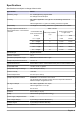
Specifications Specifications are subject to change without notice. Specification Details Measuring range 0 to 10,000 ppb freely programmable 0 to 200 ppm with K-Kit option Accuracy Non-cationic application: ± 0.1 ppb or ± 5% of reading, whichever is greater Cationic application: ± 2 ppb or 5% reading, whichever is greater Repeatability Average response times at 25°C with a maximum ΔT =15°C between channels < 0.02 ppb or 1.
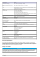
Specification Details Measurement category Cat II, Class 1 (overvoltage < 1500V) Maximum panel dimension (H x L x D) 850 x 450 x 252.5mm [33.46 x 17.71 x 9.94in] Inlet Simple fittings for 6 mm O.D. tubing or ¼" O.D. in PE-low density. ¼" OD in PHED-PTFE-SS as option Outlet Barbed stem for 12 mm (½" I.D.) hose Protection rate Transmitter: IP65 (NEMA 4) Panel: IP50 (dust protection) Optional Enclosure: IP54 (splash water proof) Instrument is designed to avoid DIPA vapor inside the enclosure.
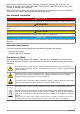
Please read this entire manual before unpacking, setting up or operating this equipment. Pay attention to all danger and caution statements. Failure to do so could result in serious injury to the operator or damage to the equipment. Make sure that the protection provided by this equipment is not impaired. Do not use or install this equipment in any manner other than that specified in this manual.
Products marked with this symbol indicates that the product contains toxic or hazardous substances or elements. The number inside the symbol indicates the environmental protection use period in years. Products marked with this symbol indicates that the product conforms to relevant South Korean EMC standards.
CAUTION Personal injury hazard. Instruments or components are heavy. Use assistance to install or move. Make sure that the wall mounting is able to hold 4 times the weight of the equipment. CAUTION Wherever the analyzer is to be mounted, it is important to note that it must be placed in an upright position with the transmitter at the top. It is recommended to use a spirit level to ensure that the analyzer is correctly positioned and not leaning to one side or forward.
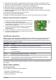
4. Unscrew the cable gland nut, pass the power cable through it, and then up through the cable gland and into the transmitter (No. 2). Screw back the cable gland nut to secure the power cable. 5. Open the transmitter front door by unscrewing the four holding screws. 6. Swing open the door (it is hinged to the left) to reveal the inside of the transmitter. 7. Remove the metallic shielding plate (No. 1) protecting access to the main board. 8. Remove the power supply connector (No.
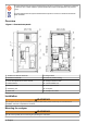
• Pressure: 0.2 to 6 bar (8-100 psig) • Sample acidity: sample acidity should not be more than 300 ppm CaCO3 • Temperature: 5 to 45°C At this stage of the installation, make sure that the flow valve is closed. Connect the pipes by inserting them into the quick release connections found on the bottom of the analyzer under the sampling block (No. 14 in Figure 1 on page 6). Be sure that the sample line is correctly flushed before any connection to avoid particle injection into the hydraulic system.
6. The flow rate for each channel should be 6 to 9 L/hour. 7. Using a screwdriver, regulate the channel’s sample flow (No. 3 in Figure 1 on page 6) by turning counter-clockwise to increase the flow rate or clockwise to decrease the flow rate. 8. The process is repeated until the flow is correctly regulated for the channel. At this point select OK. 9. The system then allows you to regulate the next channel until all flow rates have been set for the configured channels. 10.
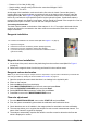
Reference electrode installation 1. Remove the reference sensor from its box. 2. Remove the plastic reservoir from the bottom (the storage solution is KCl 3M) and install the Oring as shown. 3. With care, turn the bottom electrolyte tube ferrule with a maximum ¼ turn to lock it. 4. Remove the plastic plug on the entry port. 5. Install the reference electrode in the extreme left measurement chamber (No. 2 in Figure 1 on page 6). 6.
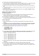
Analyzer stabilization At this stage the analyzer has been completely installed, but needs to run for a period of time to stabilize. 1. Press Start on the main menu to start the measurement process. 2. Leave the system to run for a couple of hours before starting any calibrations. User interface Function keys The display panel has 5 function keys (illustrated below) to allow menu option selection, field selection, and data entry options.
3. Press the function key under the Up Arrow or Down Arrow option to scroll through the list of available characters. 4. Press the function key under the Right Arrow option to accept the currently displayed character and move to the next character. 5. Press the Enter function key to accept the complete field and move to the next data input field.
Main menu The main menu is accessible from any one of the measurement screens. To access the main menu screen press the Up Arrow function key under the Menu option. Note: Access to the Main Menu will require a password if a PROGRAMMING password has been set (see Passwords on page 14). The first option in the menu will always be highlighted by default. To scroll to the option required, press the Up Arrow function key under the Select option.
3. The option to increase or decrease the low end value (0 mA or 4 mA depending on your setting) is displayed. Change the value up or down by selecting the Minus or Plus indicators at the bottom of the screen. 4. On completion press the Enter function key and the display changes to 20 mA. 5. Enter the adjustment value in the same way as for the low end value.
Note: If this value is set to zero, then no electrode reactivation will take place during the calibration process and as such the calibration may be inaccurate. It is highly recommended to set this parameter to 24. 4. If set to a fixed date, define the day and time of the week when reactivation takes place. Set the day of the week to an asterisk if reactivation is not to take place on that day. Datalogger setup 1. Select the VIEW DATA option to display the requested data. 2.
Relay N.O. Normally open N.C. Normally closed 5. System alarm: Alarm Relay Yes Activate the system alarm No Deactivate the system alarm N.O. Normally open N.C. Normally closed mA outputs 1. Select the mA OUTPUTS option to set up the parameters for all the analog outputs. 2. From the list available, select the mA output you wish to set. Output parameters 1. Analog output parameters: Attribute Choose the attribute that triggers the analog output.
Sample channels Select the SAMPLE CHANNELS option to set up the channel parameters. Number of channels 1. If the number of channels parameter is changed, an activation key will be required before the additional channel is recognized. Channel activation Using the Up and Down Arrow keys, define whether the channel is active (Activ) or inactive (Inactiv). Sequence The sequence defines the channel order in which samples are measured. 1. Only configured channels can be used in the sequence.
• LOW CAL SOL must be ≥ sample concentration of Na+ and a minimum of 100 ppb • HIGH CAL SOL = (LOW CAL SOL x 10) Example 1: sample concentration of Na+ = 20 ppb → LOW CAL SOL = minimum value = 100 ppb Na+ → HIGH CAL SOL = (100 ppb x 10) = 1000 ppb Na+ Example 2: sample concentration of Na+ = 450 ppb → LOW CAL SOL = ≥ sample concentration of Na+ = 500 ppb Na+ → HIGH CAL SOL = (500 ppb x 10) = 5000 ppb Na+ Note: The values LOW CAL SOL and HIGH CAL SOL must be entered into the system (see One point calibration
13. The default values of the offset and slope are displayed along with the calculated values for the last and current calibration. 14. A message is displayed indicating the success or failure of the calibration. One point calibration This process requires that a calibration solution of known sodium concentration is available. Refer to Calibration solution concentrations on page 18 for information regarding the concentration of the calibration solution. 1. Select the MAN.
7. If the mode is set to frequency, then the week and hour data fields will be replaced by a TIME PERIOD field. Enter the calibration frequency in hours into this field. 8. Finally, in the CALIB ON field, select the channel to be used for calibration. The number of channels available will depend on the number of channels configured for the instrument.
4. The reactivation process is automatically followed by a rinsing of the overflow vessel and measuring cell using the process sample. Upon completion of the rinsing step, the analyzer is ready for the first manual step in the cycle. 5. Place the lid of the overflow vessel on the side and pour approximately 200 mL of the solution into the overflow vessel, as prompted on screen. Manual introduction is complete when the sample overflows at the back of the overflow vessel. 6.
Adjust bottle volumes This option should be used to set the default values of reagents or when bottles are being used that are not full (see Bottles full on page 23). 1. Select the ADJUST BOTTLE VOLS. option to set the reagent volumes. 2. Enter the volumes for the conditioning solution, reactivation solution, calibration solution and electrolyte in milliliters. 3. Press Select to move from one field to another to keep the value displayed, or press Enter on completion of a field to move to the next. 4.
Spezifikationen Die Spezifikationen können ohne Vorankündigung Änderungen unterliegen. Spezifikation Details Messbereich 0 bis 10.000 ppb frei programmierbar 0 bis 200 ppm mit Option K-Kit Genauigkeit Nicht kationische Anwendungen: ± 0,1 ppb oder ± 5% der Anzeige, je nachdem, welcher Wert größer ist Kationische Anwendung: ± 2 ppb oder ± 5% der Anzeige, je nachdem, welcher Wert größer ist Wiederholbarkeit Durchschnittliche Reaktionszeiten bei 25°C mit max.
Spezifikation Details Verschmutzungsgrad 2 (gemäß Standard CEI 664) Höhe < 2000 m Messkategorie Kat. II, Klasse 1 (Überspannung < 1.500V) Max. Paneelabmessungen (H x L x T) 850 x 450 x 252,5 mm [33,46 x 17,71 x 9,94in] Einlass Einfache Anschlüsse für 6 mm A.D.-Leitungen oder ¼" A.D. aus LDPE ¼" AD aus PHED-PTFE-SS optional Auslass Bajonettanschluss 12 mm (½" I.D.
Sicherheitshinweise HINWEIS Der Hersteller ist nicht für Schäden verantwortlich, die durch Fehlanwendung oder Missbrauch dieses Produkts entstehen, einschließlich, aber ohne Beschränkung auf direkte, zufällige oder Folgeschäden, und lehnt jegliche Haftung im gesetzlich zulässigen Umfang ab. Der Benutzer ist selbst dafür verantwortlich, schwerwiegende Anwendungsrisiken zu erkennen und erforderliche Maßnahmen durchzuführen, um die Prozesse im Fall von möglichen Gerätefehlern zu schützen.
Elektrische Geräte, die dieses Symbol aufweisen, dürfen in Europa nicht als Haushaltsabfall entsorgt werden. Den lokalen und nationalen europäischen Bestimmungen gemäß müssen Benutzer von Elektrogeräten diese nun zur für den Benutzer kostenlosen Entsorgung an den Hersteller zurückgeben. Hinweis: Mit der Wiederverwertung, der stofflichen Verwertung oder anderen Formen der Verwertung von Altgeräten leisten Sie einen wichtigen Beitrag zum Schutz unserer Umwelt.
Installation des Analysators WARNUNG Schließen Sie die Stromversorgung nicht an, bevor das Instrument montiert und verplombt worden ist VORSICHT Verletzungsgefahr. Geräte oder Komponenten sind schwer. Bewegen oder installieren Sie diese nicht allein. Vergewissern Sie sich, dass die Wandbefestigung das vierfache Gewicht der Ausrüstung tragen kann.
4. Schrauben Sie die Mutter der Kabeldurchführung ab, führen Sie das Kabel hindurch und dann hinauf durch die Kabeldurchführung und in den Transmitter (Nr. 2). Schrauben Sie die Mutter der Kabeldurchführung wieder auf, um das Stromkabel zu sichern. 5. Öffnen Sie die Fronttür des Transmitters durch Abschrauben der 4 Halterungsschrauben. 6. Öffnen Sie die Tür (sie ist links angeschlagen), um zum Inneren des Transmitters zu gelangen. 7. Entfernen Sie die Abschirmungsplatte aus Metall (Nr.
Anschlüsse Funktion Iout0 Wird für die aktuellen Messsignale verwendet Iout1 bis Iout7 Kann frei mit unterschiedlichen Parametern wie Messung, Temperatur verknüpft werden, für detaillierte Informationen beziehen Sie sich bitte auf Abschnitt mA-Ausgänge auf Seite 39. Abschließend das lokale Steuerungsgehäuse (Nr. 11 in Abbildung 1 auf Seite 27) schließen und mit den 6 Schrauben fixieren.
1. Öffnen Sie das Probenventil und stellen Sie sicher, dass die Hydraulikleitungen keine Lecks aufweisen. 2. Schalten Sie die Stromversorgung des Analysators ein. 3. Wählen Sie die Option Menü auf der Anzeige. 4. Wählen Sie WARTUNG/DIAG. aus dem Hauptmenü und drücken Sie Enter. 5. Wählen Sie die Option WECHSEL REAGENZLÖSUNG und drücken Sie Enter. 6. Stellen Sie den Parameter FLASCHEN VOLL auf Ja ein und drücken Sie Enter. 7. Drücken Sie Esc, um zum Menü WARTUNG/DIAG. zurückzukehren.
4. Definieren Sie für jeden Kanal das Verhältnis der Gaseinspritzungszeit in Abhängigkeit von dem pH-Wert der Probe. Geben Sie diesen Wert in den Analysator ein wie in Gesamt Gas-WasserVerhältnis (nur kationische Anwendungen) auf Seite 37 beschrieben. Die Standardwerte sind: • • • • • • pH = 2.0 - Verhältnis Ggas/Gwasser = 180% pH = 2.3 - Verhältnis Ggas/Gwasser = 80% pH = 2.6 - Verhältnis Ggas/Gwasser = 50% pH = 2.9 - Verhältnis Ggas/Gwasser = 30% pH = 3.5 - Verhältnis Ggas/Gwasser = 15% pH = 4.
VORSICHT Nach dem Anschließen der Elektroden ist es sehr wichtig, dass keine der Elektrodenköpfe den unteren Teil der Messzelle berührt. Füllen des Elektrolytreservoirs Das Elektrolytreservoir befindet sich auf der Rückseite des Analysators (Nr. 12 in Abbildung 1 auf Seite 27). 1. Nehmen Sie die KCI-Elektrolytflasche und setzen Sie die Spitze des kegelförmigen Ausgusses so weit wie möglich aber ohne Druck auszuüben auf die Einlassleitung des Reservoirs. 2.
Die Dateneingabe erfolgt auf unterschiedliche Weise und ist von den Eigenschaften des entsprechenden Datenfelds abhängig. Numerische Felder Diese Felder erfordern die Eingabe eines oder mehrerer numerischer Werte in das Feld durch den Benutzer. Der Typ des Felds bestimmt die verfügbare Eingabe. In einige Felder können nur Ziffern von 0 bis 9 eingegeben werden, während in anderen Felder außerdem das Dezimalzeichen und/oder das Vorzeichen Minus verfügbar sind. 1.
Inkrementalwertfelder Dies sind Felder, in denen ein Wert auf der Bildschirmanzeige angezeigt wird, und der Benutzer hat die Option, diesen Wert anzuzeigen oder abzusenken. 1. Benutzen Sie die Funktionstaste Pfeil aufwärts unter den Symbolen Puls oder Minus, um den Wert um 1 anzuheben oder abzusenken. 2. Drücken Sie nach Abschluss die Funktionstaste Enter, um den neuen Wert zu akzeptieren. Bildschirmanzeigen Messung Hauptanzeige 1. 2. 3. 4. 5. 6.
• SYSTEMEINRICHTUNG - Siehe den Abschnitt mit dem Titel SYSTEM-SETUP auf Seite 36 SYSTEM-SETUP Datum und Uhrzeit 1. 2. 3. 4. 5. Wählen Sie die Option DATUM/UHRZEIT, um das Untermenü Datum/Uhrzeit aufzurufen. Scrollen Sie zu dem gewünschten Tag und drücken Sie dann die Funktionstaste Enter. Geben Sie den Tag, den Monat und das Jahr ein. Geben Sie die Zeit im Format SS:MM:SS (24-Stunden-Format) ein. Drücken Sie nach Abschluss Esc, um zum Menü Parameter System zurückzukehren. Optionen Anzeige 1.
BENUTZERDEFINIERTE EINRICHTUNG Messung Ziel-pH-Wert (nur für nicht kationische Anwendungen) Wählen Sie die Option pH und geben Sie den pH-Zielwert für Ihre Anwendung ein. Der gemessene pH-Wert der Probe in der Messzelle sollte innerhalb von ±0,2 pH des Zielwerts liegen. Gesamt Gas-Wasser-Verhältnis (nur kationische Anwendungen) 1. Geben Sie für jeden Kanal das Verhältnis von Gas und Wasser ein, um den DIPA-Verbrauch zu reduzieren. Hierbei handelt es sich um eine Installationsprozedur.
Einrichtung des Messwertspeichers 1. Wählen Sie die Option DATEN ANZEIGEN, um die erforderlichen Daten anzuzeigen. 2. Auf dieser Bildschirmanzeige werden alle Informationen für die in EINRICHTUNG ANZEIGE ausgewählten Parameter angezeigt. Wenn die Datenliste mehr als eine Seite umfasst, erscheint im Bildschirm unten die Taste Pfeil. Verwenden Sie die Pfeiltaste zum Scrollen der Daten. 3. Wählen Sie die Option PROG HISTORIE, um die Parameter der Daten zu definieren, die Sie anzeigen möchten. 4.
Alarm Relais Ja Aktiviert den Systemalarm. Nein Deaktiviert den Systemalarm. N.O. Einschaltglied N.C. Ausschaltglied mA-Ausgänge 1. Wählen Sie die Option AUSGÄNGE mA, um die Parameter für alle analogen Ausgänge einzustellen. 2. Wählen Sie aus der Liste den gewünschten mA-Ausgang. Ausgansparameter 1. Parameter analoger Ausgang: Wählen Sie das Attribut aus, das den analogen Ausgang auslöst.
Probenkanäle Wählen Sie die Option SAMPLE CHANNELS (Probenkanäle), um die Parameter für den Kanal einzustelllen. Anzahl der Kanäle 1. Wenn die Anzahl der Kanalparameter geändert wurde, muss ein Aktivierungsschlüssel eingegeben werden, damit der zusätzliche Kanal freigeschaltet wird. Aktivierung des Kanals Definieren Sie mit den Tasten Pfeil aufwärts und Pfeil abwärts, ob der Kanal aktiviert (Aktiv) oder deaktiviert (Inaktiv) ist.
Manuelle Kalibrierung Für eine manuelle Kalibrierung muss die Kalibrierungslösung zwischen 100 ppb und 2.000 ppm liegen und die folgenden Regeln müssen eingehalten werden: • KALIBR: LOS. N muss ≥ als die Probenkonzentration von Na+ sein und mindestens 100 ppb betragen. • KALIBR. LOS. H = (KALIBR. LOS. N x 10) Beispiel 1: Probenkonzentration von Na+ = 20 ppb → KALIBR. LOS. N = Mindestwert = 100 ppb Na+ → KALIBR. LOS. H = (100 ppb x 10) = 1.
8. Die Probe wird gemessen und die Details werden im Vergleich zu P1 angezeigt. 9. Wenn die Messung stabil ist, werden die Details oben auf der Bildschirmanzeige im Vergleich zur Messung P1 angezeigt. 10. Dann wird das Überflussgefäß gespült und erneut mit der Probe plus 20mL Kalibrierungslösung gefüllt. 11. Diese Probe wird gemessen und die Details werden im Vergleich zu P2 angezeigt. 12. Wenn die abschließende Messung stabil ist, werden der Offset und die Steigung dieser Kalibrierung berechnet. 13.
1. Wählen Sie die Option PROGRAMMIER., um das Untermenü für die Einrichtung der Kalibrierungsparameter aufzurufen. 2. Schalten Sie die automatische Kalibrierung durch die Wahl von Ja oder Nein wie gewünscht an oder aus. Bedenken Sie, dass es, auch wenn Sie Ja einstellen, trotzdem möglich ist, die Kalibrierung des Analysator bei Bedarf manuell durchzuführen. 3. KAL.SOL definiert die Konzentration der Kalibrierungslösung.
Kalibrierung der Temperatur 1. Wählen Sie die Option TEMPERATUR-KALIB., und die Temperaturelektrode zu kalibrieren. 2. Die gemessene Temperatur wird in dem Feld Raw-Temp angezeigt. 3. Nehmen Sie die Messung der Temperatur mit einem zertifizierten Thermometer vor und drücken Sie OK zum Fortfahren. 4. Geben Sie dann diese Temperatur in das Feld KAL.TEMP. ein. 5. Drücken Sie zum Kalibrieren OK.
1. Der erste Schritt ermöglicht die Reaktivierung der Elektrode. Die Meldung SENSORAKTIVIERUNG wird angezeigt. Wählen Sie Ja, um den Sensor zu reaktivieren. Wählen Sie Nein, wenn Zeit wichtiger als Präzision ist. 2. Nach dem Reaktivierungsprozess werden das Überflussgefäß und die Messzelle automatisch gespült. Nach Abschluss des Spülungsschritts ist der Analysator für den ersten manuelle Schritt des Zyklusses bereit. 3.
Behälter voll 1. Wählen Sie Ja, falls die Flaschen der Reagenzlösung voll sind, um die Defaultwerte für die Volumen einzustellen. Diese Werte können durch Wahl der Option FLASCHENVOL. EINSTELLEN im Menü angezeigt und geändert werden. Falls Sie für diese Option Nein wählen, müssen Sie die korrekten Werte mit der Option FLASCHENVOL. EINSTELLEN von Hand eingeben.
Specifiche Le specifiche sono soggette a modifica senza preavviso. Specifiche Dettagli Intervallo di misura Da 0 a 10.000 ppb liberamente programmabile Da 0 a 200 ppm con kit K opzionale Accuratezza Applicazione non cationica: ± 0,1 ppb o ± 5% della lettura, comunque il maggiore Applicazione cationica: ± 2 ppb o ± 5% della lettura, comunque il maggiore Ripetibilità < 0,02 ppb o 1,5% della lettura, comunque il maggiore entro una variazione di 10°C Tempi medi di risposta a 25°C con ΔT =15°C max.
Specifiche Dettagli Grado di inquinamento 2 (in base alla norma CEI 664) Altitudine < 2000 m Classe di misurazione Cat II, Classe 1 (sovratensione < 1500V) Dimensioni massime del pannello (A x L x P) 850 x 450 x 252,5 mm [33,46 x 17,71 x 9,94 pollici] Ingresso Raccordi semplici per tubi in PE a bassa densità con diametro esterno di 6 mm o ¼".
Informazioni sulla sicurezza AVVISO Il produttore non sarà da ritenersi responsabile in caso di danni causati dall'applicazione errata o dall'uso errato di questo prodotto inclusi, a puro titolo esemplificativo e non limitativo, i danni incidentali e consequenziali; inoltre declina qualsiasi responsabilità per tali danni entro i limiti previsti dalle leggi vigenti.
Le apparecchiature elettriche contrassegnate dal presente simbolo non possono essere smaltite nei centri pubblici di smaltimento europei. In conformità con le normative nazionali e locali europee, gli utenti di apparecchiature elettriche in Europa devono restituire gli strumenti obsoleti al produttore, il quale provvederà al loro smaltimento senza alcuna spesa a carico dell'utente.
Installazione dell'analizzatore AVVERTENZA Non collegare il cavo di alimentazione prima di avere completato le operazioni di montaggio dello strumento e di collegamento delle relative tubazioni. ATTENZIONE Pericolo di lesioni personali. Gli strumenti o i componenti sono pesanti. Per l'installazione o lo spostamento richiedere assistenza. Verificare che il fissaggio a parete sia in grado di sostenere un peso 4 volte superiore a quello dell'apparecchio.
4. Svitare il dado del pressacavo, quindi fare passare il cavo di alimentazione attraverso il dado e il pressacavo per raggiungere il trasmettitore (N. 2). Avvitare il dado del pressacavo per bloccare il cavo di alimentazione. 5. Aprire lo sportello anteriore del trasmettitore svitando le quattro viti di fissaggio. 6. Aprire lo sportello verso sinistra, facendolo ruotare sui suoi cardini, per scoprire l'interno del trasmettitore. 7. Rimuovere la piastra di schermatura metallica (N.
Collegamenti Funzione Da In4 a In7 Bypassare la misura sul canale (canale 4 - 1) Iout0 Utilizzato per i segnali di misurazione corrente Da Iout1 a Iout7 Possono essere liberamente collegate a parametri diversi quali misurazione e temperatura fare riferimento alla sezione Uscite mA a pagina 62 per i dettagli Al termine, chiudere l'alloggiamento del controller locale (N. 11 nella Figura 1 a pagina 50) e bloccarlo in posizione con 6 viti.
1. Aprire la valvola di campionamento e verificare che non vi siano dispersioni nel percorso idraulico. 2. Accendere l'analizzatore. 3. Selezionare l'opzione Menu sul display. 4. Selezionare MANUTENZ./DIAGNOSI nel menu principale e premere Enter. 5. Selezionare l'opzione SOSTITUZ. REAGENTI e premere Enter. 6. Impostare il parametro TANICHE PIENE a Sì e premere Enter. 7. Premere Esc per tornare al menu MANUTENZ./DIAGNOSI. Regolazione della portata 1. Dal menu MANUTENZ.
• • • • • • pH = 2.0 - Tgas/Tacqua ratio = 180% pH = 2.3 - Tgas/Tacqua ratio = 80% pH = 2.6 - Tgas/Tacqua ratio = 50% pH = 2.9 - Tgas/Tacqua ratio = 30% pH = 3.5 - Tgas/Tacqua ratio = 15% pH = 4.0 - Tgas/Tacqua ratio = 10% 5. Installare lo stesso sensore per pH al centro della camera di misura (N. 2 nella Figura 1 a pagina 50). 6. Sull'analizzatore, premere Start sul menu principale per avviare il processo di misurazione. 7.
Riempimento del serbatoio dell'elettrolita Il serbatoio dell'elettrolita è installato sul retro dell'analizzatore (N. 12 nella Figura 1 a pagina 50). 1. Prendere il flacone di elettrolita KCI e inserire a fondo la punta della cannuccia nel tubo di ingresso del serbatoio senza esercitare una pressione eccessiva. 2. Schiacciare il flacone fino a riempire il serbatoio a circa 3/4 della sua capacità.
4. Premere il tasto funzione in corrispondenza dell'opzione Freccia verso il basso per ridurre il valore del campo di 1. 5. Premere il tasto funzione in corrispondenza dell'opzione Freccia verso destra per confermare il numero visualizzato e spostare il cursore di una cifra verso destra. 6. Premere il tasto funzione Enter per confermare i dati e spostarsi sul campo di immissione successivo. Campi alfanumerici Questi campi richiedono l'immissione di uno o più valori alfanumerici.
Schermate di misurazione Display principale 1. 2. 3. 4. 5. 6. Campione in fase di misurazione Barra indicante l'avanzamento della misurazione Grafico della misurazione corrente Ora Misura corrente e unità Temperatura Sulla parte inferiore della schermata appaiono tre delle seguenti opzioni: • Stori - selezionando questa opzione appariranno le ultime misurazioni unitamente ai dati di verifica e del campione esterno. • Stop - selezionare questa opzione per interrompere il processo in corso.
4. Immettere l'ora nel formato HH:MM:SS (24 ore). 5. Al termine, premere Esc per tornare al menu Configuraz. sistema. Opzioni di visualizzazione 1. Selezionare l'opzione DISPLAY per configurare i parametri di visualizzazione. 2. Selezionare i campi LINGUA, UNITÀ CONC. e LIMITE DI TEMP. e impostare il valore desiderato scorrendo tra le voci disponibili. Password 1. Selezionare l'opzione PASSWORD per impostare le password per l'accesso alle opzioni Programmazione, Taratura e Configurazione sistema. 2.
CONFIGURAZIONE UTENTE Misura pH target (solo applicazioni non cationiche) Selezionare l'opzione pH e impostare il valore del pH target per l'applicazione. Il valore pH del campione nella cella di misura deve corrispondere a quello target, con un'oscillazione di ± 0,2 pH. Rapporto gas/acqua totale (solo applicazioni cationiche) 1. Per ogni canale, impostare il rapporto tra acqua e gas che consente di ridurre al minimo il consumo di DIPA.
Setup datalogger 1. Selezionare l'opzione VISTA DATI per visualizzare i dati richiesti. 2. Nella schermata appaiono tutte le informazioni corrispondenti ai parametri selezionati nella finestra SETUP VISTA. Se i dati occupano più di una schermata, un tasto Freccia appare nella parte inferiore dello schermo. Utilizzare questo tasto per scorrere i dati. 3. Selezionare l'opzione SETUP VISTA per definire i parametri per i dati che si desidera visualizzare. 4.
Relè N.O. Normalmente aperto N.C. Normalmente chiuso 5. Allarme di sistema: Allarme Relè Sì Attiva l'allarme di sistema No Disattiva l'allarme di sistema N.O. Normalmente aperto N.C. Normalmente chiuso Uscite mA 1. Selezionare l'opzione USCITA mA dal menu principale per impostare i parametri delle uscite analogiche. 2. Nell'elenco, selezionare l'uscita mA che si desidera impostare. Parametri dell'uscita 1.
Test Questa opzione consente di impostare un valore nel campo mA. Premere il tasto funzione Enter per applicare questo valore a tutte le uscite analogiche. Il valore può quindi essere verificato con l'uso di un multimetro collegato all'analizzatore. RS485 (o PROFIBUS) Nota: Se è installato il modulo opzionale PROFIBUS, sul menu appare l'opzione PROFIBUS anziché RS485, e l'utente dovrà impostare i parametri PROFIBUS. 1. Selezionare l'opzione RS485 per impostare i parametri del protocollo di comunicazione.
• Calibrazione manuale - L'utente può eseguire manualmente la calibrazione quando necessario. • Calibrazione automatica - È possibile impostare i parametri di modo che l'analizzatore esegua automaticamente la calibrazione all'ora e nei giorni prestabiliti (vedere Impostazione della calibrazione automatica a pagina 66). Questo tipo di calibrazione richiede l'impiego di una soluzione la cui concentrazione è nota. Nota: Prima di avviare la calibrazione è importante verificare che il parametro Freq. attiv.
soluzione di calibrazione è definita nella Impostazione della calibrazione automatica a pagina 66. 2. Lo strumento verifica che la quantità di soluzione di calibrazione rimasta sia sufficiente. Se non lo fosse, un allarme di avvertimento si attiva e lo strumento ripristina la modalità di misurazione normale utilizzando i parametri originali. 3. Se il volume di soluzione è adeguato, viene eseguita la misurazione del punto di riferimento (P0).
Calibrazione su due punti Questo processo richiede l'utilizzo di due soluzioni di calibrazione la cui concentrazione di sodio sia conosciuta. Fare riferimento a Concentrazioni della soluzione di calibrazione a pagina 64 per informazioni inerenti alle concentrazioni della soluzione di calibrazione. 1. Selezionare l'opzione CAL.MAN ZERO+SLOPE per avviare la calibrazione su due punti. 2.
Per i dettagli dei risultati di calibrazione, selezionare l'opzione Registri calibrazione, come illustrato di seguito. Registri calibrazione 1. Selezionare l'opzione REGISTRI CALIBRAZIONE per visualizzare le informazioni inerenti le calibrazioni eseguite in precedenza. 2. Usare il tasto Freccia per scorrere i dati. Regolazione personalizzata 1. Quando l'analizzatore visualizza dei valori che sono leggermente superiori o inferiori al valore previsto, l'opzione CUSTOM.
8. Al termine del ciclo, l'analizzatore si predispone automaticamente in modalità di misurazione standard. 9. Selezionare Princ per tornare alla schermata di misurazione principale. CAMPIONE ESTERNO Simile al processo di verifica, questa opzione consente la misurazione di un campione a propria scelta. Prima di avviare la procedura, accertarsi di avere a disposizione circa 200 mL di campione da misurare.
Spurgo tubi 1. Dopo avere riempito i flaconi (elettrolita di riferimento, soluzione di calibrazione e soluzione di riattivazione) e/o avere sostituito il flacone vuoto di reagente di condizionamento con uno nuovo, selezionare l'opzione SPURGO TUBI. Si avvierà il processo di spurgo e riempimento dei tubi. 2. Premere il tasto funzione Esc per annullare l'operazione e tornare al menu. Taniche piene 1. Se i flaconi di reagente sono pieni, selezionare Sì per impostare i volumi predefiniti.
Spécifications Les spécifications peuvent faire l’objet de modifications sans préavis.
Spécification Détails Degré de pollution 2 (suivant norme CEI 664) Altitude < 2000 m Catégorie de mesure Cat II, Classe 1 (surtension < 1500V) Dimension maximale panneau (H x l x P) 850 x 450 x 252,5mm [33.46 x 17.71 x 9.94in] Entrée Raccords simples pour tube diam. ext. 6 mm ou diam. ext. ¼" en PE faible densité Diam. ext. ¼" en PHED-PTFE-SS en option Sortie Raccord annelé pour flexible diam. int.
Consignes de sécurité AVIS Le fabricant décline toute responsabilité quant aux dégâts liés à une application ou un usage inappropriés de ce produit, y compris, sans toutefois s'y limiter, des dommages directs ou indirects, ainsi que des dommages consécutifs, et rejette toute responsabilité quant à ces dommages dans la mesure où la loi applicable le permet.
Les équipements électriques identifiés par ce symbole ne doivent pas être éliminés dans des décharges publiques européennes. Conformément aux réglementations européennes locales et nationales, les utilisateurs d'équipements électriques européens doivent maintenant retourner les équipements anciens ou en fin de vie au fabricant en vue de leur élimination sans frais pour l'utilisateur.
Montage AVERTISSEMENT L'analyseur ne doit être assemblé que par du personnel qualifié. L'alimentation ne doit être branchée qu'après la fin de l'installation et de la vérification Montage de l'analyseur AVERTISSEMENT Ne raccordez pas l’instrument au secteur avant de le monter et d’effectuer les raccordements de tuyauteries. ATTENTION Risque de blessures. Les instruments ou les composants sont lourds. Ne les installez ou ne les déplacez pas tout seul.
3. Dévissez les deux vis de retenue en haut à gauche et en haut à droite du boîtier et laissez-le pivoter vers le bas pour accéder à l'arrière de l'émetteur. Le passe-câble pour le câble d'alimentation est celui qui se trouve à gauche le plus proche de vous. 4. Dévissez l'écrou du passe-câble, faites y passer le câble d'alimentation, puis passez-le à travers le passe-câble pour arriver dans l'émetteur (n° 2). Revissez l'écrou du passe-câble pour fixer le câble d'alimentation. 5.
Connexions Fonction In2 Pour l'étalonnage à distance In4 à In7 Supprimer la mesure du canal (canal 4 - 1) Iout0 Utilisé pour les signaux de mesure de courant Iout1 à Iout7 Peuvent être rattachées librement à différents paramètres comme les mesures, la température – se reporter au chapitre intitulé Sorties mA à la page 85 pour plus de détails Une fois terminé, refermez le boîtier du contrôleur local (nº 11 sur la Figure 1 à la page 73) et fixez-le avec les 6 vis.
Déclaration du volume des réactifs Remarque : Puisque vous utiliserez maintenant les menus de l'analyseur pour saisir les données, il peut être utile de vous familiariser avec les procédures de saisie des données en lisant la section intituléeInterface utilisateur à la page 79. 1. 2. 3. 4. 5. 6. 7. Ouvrez la vanne d’échantillon et vérifiez qu’il n’y a aucune fuite dans le passage hydraulique. Mettez l’analyseur sous tension. Sélectionnez l’option Menu à l'écran. Sélectionnez MAINTENANCE/DIAG.
4. Déterminez pour chaque canal le taux de durée d'injection de gaz en fonction du pH de l'échantillon. Saisissez cette valeur dans l'analyseur comme décrit à la section Taux Gaz/Eau total (applications cationiques uniquement) à la page 83. Les valeurs standard sont : • • • • • • pH = 2.0 - Tgaz/Teau ratio = 180% pH = 2.3 - Tgaz/Teau ratio = 80% pH = 2.6 - Tgaz/Teau ratio = 50% pH = 2.9 - Tgaz/Teau ratio = 30% pH = 3.5 - Tgaz/Teau ratio = 15% pH = 4.0 - Tgaz/Teau ratio = 10% 5.
ATTENTION Après l'installation des électrodes, il est très important qu'aucune des têtes des électrodes ne touche la partie inférieure de la cellule de mesure. Remplissage du réservoir à électrolyte Le réservoir à électrolyte est situé à l'arrière de l'analyseur (n° 12 sur la Figure 1 à la page 73). 1. Introduisez le plus possible (mais sans exercer de pression supplémentaire) la pointe du bec fuselé de la bouteille d'électrolyte dans le tube d'entrée du réservoir. 2.
La saisie de données est effectuée de diverses façons en fonction des caractéristiques du champ de données auquel on accède. Champs numériques Ces champs imposent que l’utilisateur saisisse une ou plusieurs valeur(s) numérique(s) dans un champ. Le type de champ détermine l’entrée possible. Dans certains champs, les chiffres de 0 à 9 uniquement peuvent être sélectionnés alors que dans d’autres champs la virgule décimale et/ou le signe moins peut aussi être disponible. 1.
Champs à valeur incrémentielle Il existe des champs dans lesquels une valeur est affichée sur l’écran et l’utilisateur a la possibilité d’augmenter ou de diminuer la valeur. 1. Utilisez les touches de fonction Flèche vers le haut sous les symboles plus ou moins pour augmenter ou diminuer la valeur de 1. 2. À la fin, appuyez sur la touche de fonction Enter, pour accepter la nouvelle valeur. Écrans de mesure Écran principal 1. 2. 3. 4. 5. 6.
CONFIG. SYSTÈME Date et heure 1. 2. 3. 4. 5. Sélectionnez l’option DATE/HEURE pour accéder au sous-menu date/heure. Faites défiler jusqu’au jour voulu et appuyez sur la touche de fonction Enter. Saisissez le jour, le mois et l’année. Saisissez l’heure au format HH:MM:SS (24 heures). Une fois terminé, appuyez sur Esc pour retourner au menu principal de paramétrage du système. Options d'affichage 1. Sélectionnez l’option AFFICHAGE pour régler les paramètres d’affichage. 2.
PARAMÉTRAGE UTILISATEUR Mesure pH cible (applications non-cationiques uniquement) Sélectionnez l’option pH et saisissez la valeur du pH cible pour votre application. La valeur mesurée du pH de l’échantillon dans la cellule de mesure doit être comprise entre ±0,2 pH de la valeur cible. Taux Gaz/Eau total (applications cationiques uniquement) 1. Saisissez le taux de gaz sur eau pour chaque canal pour réduire la consommation de DIPA.
Configuration de l'enregistreur de données 1. Sélectionnez l’option VISUALISATION DONNÉES pour afficher les données demandées. 2. Toutes les informations correspondant aux paramètres sélectionnés dans l’option PROG.VISUALISATION s’affichent sur l’écran. Si les données occupent plus d'un écran, une touche Flèche sera affichée au bas. Utilisez cette touche pour faire défiler les données. 3. Sélectionnez l’option PROG.VISUALISATION pour définir les paramètres des données que vous souhaitez visualiser. 4.
Relais N.O. Normalement ouvert N.F. Normalement fermé 5. Alarme système : Alarme Relais Oui Active l’alarme d’avertissement Non Désactive l’alarme d’avertissement N.O. Normalement ouvert N.F. Normalement fermé Sorties mA 1. Sélectionnez l’option SORTIES mA pour établir les paramètres de toutes les sorties analogiques. 2. Sélectionnez la sortie mA que vous souhaitez mettre à jour dans la liste. Paramètres de sortie 1.
Test Cette option vous permet de saisir une valeur dans le champ mA. Appuyez sur la touche de fonction Enter pour forcer cette valeur sur toutes les sorties analogiques. La valeur peut alors être vérifiée à l’aide d’un multimètre connecté à l’analyseur. RS485 (ou PROFIBUS) Remarque : Si l'option PROFIBUS a été installée, l'option du menu affichera PROFIBUS au lieu de RS485 et les paramètres PROFIBUS devront être configurés. 1.
• Étalonnage manuel - L’utilisateur peut effectuer un étalonnage manuel en fonction des besoins. • Étalonnage automatique – Les paramètres peuvent être définis pour que l’analyseur effectue un étalonnage automatiquement à des jours et heures prédéfinis (voir Paramétrage d'étalonnage automatique à la page 89). Ce type d’étalonnage est toujours effectué en utilisant des concentrations connues de solution d’étalonnage.
Lancer l’étalonnage Sélectionnez l’option DÉPART ÉTALONNAGE pour étalonner l’analyseur manuellement. Étalonner un ajout connu 1. Sélectionnez l’option ÉTAL. AJOUT CONNU pour étalonner l’analyseur en mélangeant l’échantillon à une solution d’étalonnage de concentration connue. La concentration de la solution d’étalonnage est définie dans Paramétrage d'étalonnage automatique à la page 89. 2. L’instrument vérifie d’abord que le volume de la solution d’étalonnage restante est suffisant.
Étalonnage deux points Ce processus exige que deux solutions d’étalonnage de concentrations sodium connues soient disponibles. Reportez-vous à Concentrations de la solution d'étalonnage à la page 87 pour plus d'informations concernant les concentrations de la solution d'étalonnage. 1. Sélectionnez l’option ÉTAL. DÉV.+PENTE MAN. pour lancer le processus d’étalonnage à deux points. 2. Si nécessaire, saisissez les concentrations des solutions d’étalonnage, et sélectionnez DÉPART pour démarrer le processus.
Si l’étalonnage est rejeté, une alarme est déclenchée et les paramètres restent inchangés. Après un court délai, l'analyseur revient eu mode de fonctionnement normal. Pour les détails des résultats d’étalonnage, sélectionnez l’option historique d’étalonnage comme décrit ci-après. Historique des étalonnages 1. Sélectionnez l’option HISTORIQUE ÉTALON. pour visualiser l’historique des étalonnages précédents. 2. Utilisez la touche Flèche pour faire défiler les données. Ajustement personnalisé 1.
La valeur affichée dans écart, est la différence de pourcentage entre la concentration de la solution de vérification saisie dans le champ SOL. VALID. et la concentration mesurée par l’instrument. Si cette valeur est trop élevée, alors un étalonnage de l’analyseur est recommandé. 8. Lorsque le cycle est terminé, l’analyseur revient automatiquement au mode de mesure standard. 9. Sélectionnez Princ pour revenir à l’écran principal de mesure.
Amorçage des tubes 1. Après remplissage des bouteilles (électrolyte de référence, solution d’étalonnage et solution de réactivation) et/ou après remplacement d’une bouteille vide de réactif de conditionnement par une nouvelle, sélectionnez l’option AMORÇAGE TUBES. Cela désactive le processus pour purger et remplir les tuyaux. 2. Appuyez sur la touche de fonction Esc à tout moment pour interrompre le processus et retourner au menu. Bouteilles pleines 1.
Especificaciones Las especificaciones están sujetas a cambios sin previo aviso. Especificación Detalles Intervalo de medición De 0 a 10.
Especificación Detalles Categoría de sobretensión 2 (según la norma EN 61010-1) Grado de polución 2 (según la norma CEI 664) Altitud < 2000 m Categoría de medición Cat. II, Clase 1 (sobretensión < 1500 V) Dimensiones máximas de panel (A x L x P) 850 x 450 x 252,5 mm [33,46 x 17,71 x 9,94 pulgadas] Entrada Conectores simples para tubos de 6 mm o ¼" de diámetro exterior de PE de densidad baja.
Información de seguridad AVISO El fabricante no es responsable de los daños provocados por un mal uso o aplicación incorrecta del producto. Entre estos daños se incluyen, sin limitación, los daños directos y accidentales. El usuario sólo es responsable de identificar los riesgos críticos de aplicación y de instalar adecuadamente los mecanismos para proteger los procesos en caso de que el equipo no funcione correctamente. Lea todo el manual antes de desembalar, instalar o trabajar con este equipo.
El equipo eléctrico marcado con este símbolo no se puede desechar en sistemas públicos de desecho europeos. A tenor de la normativa europea local y nacional, los usuarios europeos de equipos eléctricos deben enviar el equipo obsoleto al fabricante para su desecho sin cargo alguno para el usuario. Nota: Para devolver equipos para su reciclaje, póngase en contacto con el fabricante o distribuidor para así obtener instrucciones acerca de cómo devolverlos y desecharlos correctamente.
Instalación ADVERTENCIA El analizador solo puede montarlo personal cualificado. Únicamente debe conectarse a la red eléctrica después de que haya finalizado la instalación y esta se haya comprobado Montaje del analizador ADVERTENCIA No conecte el instrumento a la alimentación antes de montarlo e instalarlo. PRECAUCIÓN Peligro de lesión personal. Los instrumentos o los componentes son pesados. Pida ayuda para instalarlos o moverlos.
3. Desatornille los dos tornillos de sujeción en la parte superior izquierda y en el lateral derecho de la caja y deje que gire hacia abajo para que se muestre el posterior del transmisor. La válvula del cable de alimentación se encuentra a la izquierda próxima a usted. 4. Desatornille la tuerca de la válvula del cable, pase el cable de alimentación por ella y después arriba a través de la válvula de cable y dentro del transmisor N.º 2).
Conexiones Función Re8 Alarma del sistema In2 Para la calibración remota In4 a In7 Bypass canal de medición (canal 4 - 1) Iout0 Sirve para las señales de medición de la corriente Iout1 a Iout7 Se pueden vincular libremente a diferentes parámetros, como medición o temperatura consulte la sección titulada Salidas de mA en la página 108 para obtener más información Al finalizar, cierre la caja del controlador local N.º 11 in Figura 1 en la página 96) y fíjela en su sitio con los 6 tornillos.
Declaración del volumen de los reactivos Nota: Puesto que ahora utilizará los menús del analizador para introducir datos, puede resultarle útil familiarizarse con los procedimientos de introducción de datos mediante la lectura de la sección Interfaz de usuario en la página 102. 1. 2. 3. 4. 5. 6. 7. Abra la válvula de muestras y compruebe que no hay fugas en el vía hidráulica. Encienda el analizador. Selecciones la opción Menú en la pantalla.
4. Determine el ratio de tiempo de inyección de gas para cada canal en función del pH de la muestra. Introduzca este valor en el analizador como se describe en Ratio total de gas/agua (solo aplicaciones catiónicas) en la página 106. Los valores estándar: • • • • • • pH = 2.0 - Tgas/Tagua ratio = 180% pH = 2.3 - Tgas/Tagua ratio = 80% pH = 2.6 - Tgas/Tagua ratio = 50% pH = 2.9 - Tgas/Tagua ratio = 30% pH = 3.5 - Tgas/Tagua ratio = 15% pH = 4.0 - Tgas/Tagua ratio = 10% 5.
PRECAUCIÓN Después de la instalación de los electrodos, es muy importante que ninguno de los cabezales del electrodo toque la parte inferior de la celda de medición. Relleno del depósito de electrolitos El depósito de electrolitos se encuentra en la parte posterior del analizador (n°. 12 de la Figura 1 en la página 96). 1. Tome el frasco de electrolitos KCI e inserte la punta del surtidor en el tubo de entrada del depósito hasta el máximo pero sin ejercer una presión adicional. 2.
La introducción de datos se puede realizar de varias formas según las características del campo de datos al que se acceda. Campos numéricos Estos campos requieren que el usuario introduzca uno o varios valores numéricos. El tipo de campo determina el tipo de valor que se puede introducir. En algunos campos solo se pueden introducir dígitos del 0 al 9 mientras que en otros campos se pueden introducir números decimales y/o de signo negativo. 1.
Campos de valores incrementales Hay campos donde se muestra un valor en la pantalla y el usuario puede aumentarlo o disminuirlo. 1. Use las teclas de función de flecha arriba bajo los símbolos más o menos para aumentar o disminuir el valor en 1. 2. Cuando finalice, pulse la tecla de función Enter para aceptar el nuevo valor. Pantallas de medición Pantalla principal 1. 2. 3. 4. 5. 6.
CONFIG SISTEMA Fecha y hora 1. 2. 3. 4. 5. Seleccione la opción FECHA Y HORA para acceder al submenú de fecha y hora. Desplácese al día necesario y pulse la tecla de función Enter. Introduzca el día, mes y año. Especifique la hora con formato de HH:MM:SS (24 horas). Cuando finalice, pulse Esc para volver al menú principal Configuración del sistema. Opciones de pantalla 1. Seleccione la opción PANTALLA para configurar los parámetros de visualización en la pantalla. 2.
CONFIGURACIÓN DEL USUARIO Medición pH objetivo (solo aplicaciones no catiónicas) Seleccione la opción pH e introduzca el valor de pH objetivo para su aplicación. El valor de pH medido de la muestra en la celda de medición debe ser ±0,2 pH del objetivo. Ratio total de gas/agua (solo aplicaciones catiónicas) 1. Para cada canal, introduzca el ratio de gas/agua para minimizar el consumo de DIPA. Esto forma parte del procedimiento de instalación y se explica detalladamente en el manual de usuario completo.
Configuración de registro de datos 1. Seleccione la opción VER DATOS para mostrar los datos solicitados. 2. Aparecerá en la pantalla toda la información coincidente con los parámetros seleccionados en la opción CONFIGURACIÓN DE VISTA. Si los datos ocupan más de una pantalla, habrá disponible una tecla de flecha en la parte inferior de la pantalla. Use esta tecla para desplazarse por los datos. 3. Seleccione la opción CONFIGURACIÓN DE VISTA para definir los parámetros de los datos que desea ver. 4.
Relé N.O. Por lo general abierto. N.C. Por lo general cerrado. 5. Alarma del sistema: Alarma Relé Sí Se activa la alarma del sistema. No Se desactiva la alarma del sistema. N.O. Por lo general abierto. N.C. Por lo general cerrado. Salidas de mA 1. Seleccione la opción SALIDAS DE mA para configurar los parámetros de todas las salidas analógicas. 2. En la lista disponible, seleccione la salida de mA que desee configurar. Parámetros de salida 1.
Prueba Esta opción le permite introducir un valor en el campo mA. Pulse la tecla de función Enter para forzar este valor en todas las salidas analógicas. El valor se puede verificar posteriormente con un multímetro conectado al analizador. RS485 (o PROFIBUS) Nota: Si se ha instalado la opción PROFIBUS, la opción de menú mostrará PROFIBUS en lugar de RS485 y deberán configurarse los parámetros de PROFIBUS. 1. Seleccione la opción RS485 para configurar los parámetros del protocolo de comunicación. 2.
Nota: Antes de iniciar una calibración, es muy importante asegurarse de que el parámetro Frecuencia de reactivación (consulte Frecuencia de reactivación en la página 106) es mayor que cero (0). Si se ajusta en cero, el proceso de reactivación de electrodos no se ejecutará durante la calibración y, por ello, es posible que se obtengan resultados de medición fuera de los límites.
4. La medición debe ser estable e inferior a 1 por mil de la concentración de solución de concentración; en caso contrario, el instrumento volverá al modo de medición normal con los parámetros originales. Si la medición es correcta, se mostrarán los detalles de la medición P0 en la pantalla. 5. Si el parámetro de frecuencia de reactivación no es cero (0) [tal como se recomienda], el electrodo se reactivará. 6.
el recipiente de caudal sobrante se enjuaga y se le solicita que lo llene con la solución de calibración de valor máximo. 4. Aparece un mensaje que indica si la calibración se ha realizado correcta o incorrectamente. Configuración de calibración automática Esta opción permite calibrar automáticamente el analizador en intervalos predefinidos y periódicos.
Ajuste personalizado 1. Cuando el analizador muestra valores ligeramente superiores o inferiores al valor esperado, se puede usar la opción AJUSTE PERSONALIZADO para ajustar manualmente el valor de medición. 2. Introduzca el valor positivo o negativo que se añadirá al valor de medición. Esta opción solo se puede usar para realizar pequeños ajustes. El valor de ajuste permitido es entre -0,1 ppb y +0,1 ppb. 3.
MUESTRA DE SEDIMENTO De forma similar al proceso de verificación, esta opción permite la medición de una muestra de su elección. Antes de iniciar este proceso, asegúrese de disponer de una muestra de aproximadamente 200 ml que medir. Nota: Se recomienda que la muestra de sedimento tenga una concentración de > 10 ppb y la misma temperatura que durante la calibración para que la precisión sea lo mejor posible.
seleccione la opción PREPARAR TUBOS. Esto desactivará el proceso para purgar y rellenar los tubos. 2. Pulse la tecla de función Esc en cualquier momento para anular el proceso y volver al menú. Frascos llenos 1. Si los frascos de reactivo están llenos, seleccione Sí y se configurarán los valores predeterminados de los volúmenes. Estos valores se pueden ver y modificar seleccionando la opción AJUSTAR VOLÚMENES DE FRASCO en el menú.
Teknik Özellikler Teknik özellikler, önceden bildirilmeksizin değiştirilebilir. Teknik Özellikler Ayrıntılar Ölçüm aralığı 0 'dan 10,000 ppb 'ye kadar serbestçe programlanabilir K-Kit seçenekli 0 'dan 200 ppm 'e kadar Doğruluk Katyonik -olmayan uygulama: ± 0.1 ppb veya ± % 5 'lik bir okuma, hangisi daha büyük ise Katyonik uygulama: ± 2 ppb veya ± % 5 'lik bir okuma, hangisi daha büyük ise Tekrarlanabilirlik Kanallar arasında, azami ?T =15°C'de, 25°C'de ortalama tepki süreleri < 0.02 ppb veya % 1.
Teknik Özellikler Ayrıntılar Yükseklik < 2000 m Ölçüm kategorisi Kategori II, Sınıf 1 (aşırı gerilim < 1500V) Maksimum panel ebadı (E x B x Y) 850 x 450 x 252.5mm [33.46 x 17.71 x 9.
Güvenlik bilgileri BİLGİ Üretici, doğrudan, arızi ve sonuç olarak ortaya çıkan zararlar dahil olacak ancak bunlarla sınırlı olmayacak şekilde bu ürünün hatalı uygulanması veya kullanılmasından kaynaklanan hiçbir zarardan sorumlu değildir ve yürürlükteki yasaların izin verdiği ölçüde bu tür zararları reddeder. Kritik uygulama risklerini tanımlamak ve olası bir cihaz arızasında prosesleri koruyabilmek için uygun mekanizmaların bulunmasını sağlamak yalnızca kullanıcının sorumluluğundadır.
Bu simge ile işaretlenen elektrik ekipmanı, Avrupa kamusal atık sistemleri ile atılamaz. Avrupa yerel ve ulusal düzenlemelerine göre Avrupa'daki elektrik cihazı kullanıcıları, artık eski ya da çalışma ömrünü doldurmuş cihazları, kullanıcıya hiçbir ekonomik yükümlülük gelmeksizin atık işlemleri için üreticiye iade etmelidirler.
Kurulum UYARI Analiz cihazı, ancak nitelikli personel tarafından kurulmalıdır. Şebeke gücü ancak kurulum tamamlandıktan ve gözden geçirildikten sonra bağlanmalıdır. Analiz cihazının yerleştirilmesi UYARI Cihazı yerleştirmeden ve pompalama öncesinde enerjiyi bağlamayınız. DİKKAT Kişisel yaralanma tehlikesi. Cihazlar veya bileşenler ağırdır. Kurarken veya taşırken yardım alın. Duvar montajının aygıt ağırlığının 4 katına kadar taşıyabildiğinden emin olun.
4. Kablo başlığının somununu sökünüz, güç kablosunu bunun içerisinden ve sonra da kablo kablo başlığınının da içerisinden geçirip, vericinin içine geçiriniz (No. 2). açığa çıkarmak üzere ön paneli kaldırıp ayırın. Kablo başlığının somununu güç kablosunu sabitlemek üzere, yerine geri vidalayınız. 5. Vericinin ön kapağını tutucu dört adet vidayı sökerek açınız. 6. Vericinin iç kısmının açığa çıkması için, kapağı açınız (soldan menteşelidir). 7. Koruyucu metal levhayı sökünüz (No.
Bağlantılar İşlev In4 'ten In7'ye kadar Kanal ölçümünün baypaslanması (sırasıyla kanal 4 - 1) Iout0 O andaki ölçüm sinyalleri için kullanılır Iout1 'tan Iout7'e kadar Ölçüm, sıcaklık gibi farklı parametrelere serbestçe bağlantı yapılabilir - ayrıntılar için mA çıkışlar sayfa 130 başlıklı bölüme başvurunuz. Tamamlandığında, yerel denetleyici kutusunu (No. 11; Şekil 1 sayfa 119) kapatınız ve 6 vida ile yerine sabitleyiniz.
1. 2. 3. 4. 5. 6. 7. Numune valfını açınız ve hidrolik yolu üzerinde herhangi sızma olup olmadığını kontrol ediniz. Analiz cihazına enerji verilmesi. Ekrandan, Menu seçeneğini seçiniz. Ana menüden MAINTENANCE/DIAG.(BAKIM/TEŞHİS) seçiniz ve ENTER üzerine basınız. REAGENT CHANGES seçeneğini seçiniz ve Enter basınız. BOTTLES FULL (ŞİŞELER DOLU) parametresini belirleyiniz Yes seçiniz ve Enter basınız. Esc basarak MAINTENANCE/DIAG menüsüne geri dönünüz. Akış hızı ayarlaması 1. MAINTENANCE/DIAG.
• • • • • • pH = 2.0 - Tgaz/Tsu oranı = %180 pH = 2.3 - Tgaz/Tsu oranı = %80 pH = 2.6 - Tgaz/Tsu oranı = %50 pH = 2.9 - Tgaz/Tsu oranı = %30 pH = 3.5 - Tgaz/Tsu oranı = %15 pH = 4.0 - Tgaz/Tsu oranı = %80 5. Aynı pH sensörünü, ölçüm odacığı (haznesi) merkez konumuna yerleştiriniz (No. 2; Şekil 1 sayfa 119). 6. Analiz cihazı üzerinde ölçüm sürecini başlatmak için, Start (Başlat) basınız. 7. Her bir kanal için, pompa oranlarının (hızlarının) 11.
Elektrolit haznesinin doldurulması Elektrolit haznesi, analiz cihazının arkasında yer alır (No. 12; Şekil 1 sayfa 119). 1. KCl elektrolit şişesini alınız ve ucu sivriltilmiş ağzının girişini, haznenin giriş ağzı borusuna, fazladan herhangi bir basınç uygulamaksızın, gidebildiği kadar ileriye doğru sokunuz. 2. Hazneyi kapasitesinin 3/4'üne kadar doldurmak üzere gerektiği kadar tekrarla şişenin üzerinden sıkınız.
5. O anda görüntülenen karakter hanesini kabul etmek ve bir sonraki haneye gitmek için, Right Arrow seçenekleri altındaki fonksiyon tuşuna basınız. 6. Alanı kabul etmek ve bir sonraki veri giriş alanına gitmek için, Enter fonksiyon tuşuna basınız. Alfasayısal alanlar Bu alanlar, kullanıcının bir alana bir ya da daha fazla alfasayısal değerler girmesini gerektirir. Alanın cinsi, kullanılabilir girişi belirler.
Ekranın alt kısmında yer alan seçenekler, aşağıdakilerin üçünü içerir: • Hist - Bu seçeneğin seçilmesi, son elde edilen numune ve doğrulama ayrıntıları ile birlikte, en yeni ölçümleri gösterir. • Stop - Bu seçeneğin seçilmesi, o anda analiz cihazı üzerindeki süreci durdurur. Bu, bir ölçüm, doğrulama veya yakalanan numune süreci olabilir. Bu seçenek ancak işbu süreçlerden biri o esnada çalışır durumda olduğunda kullanılabilirdir.
Şifreler 1. Programlama, kalibrasyon ve sistem kurulum (ayar) seçeneklerine erişim için, PASSWORDS (ŞİFRELER) seçeneğini seçiniz. 2. Her bir şifre, 4-haneli sayısal bir alandır. Üç şifrenin her biri için gerekli değeri giriniz. 0000 değeri, bu menü seçeneklerine erişim için herhangi bir şifrenin gerekli olmadığını işaret eder. Varsayılan değerler 1. Daha önce seçilmiş tüm kullanıcı parametrelerini silmek ve varsayılan değerleri yüklemek için, DEFAULT VALUES seçeneğini seçiniz.
Ölçüm adımları - çok kanal 1. Çevrim-içi ölçüm zamanı, analiz cihazının doğru sodyum ölçümünü görüntülediği andır. Bu değer, en azından 1 dakika ve döngü süresinden daha kısa olmalıdır. 2. Eğer bir kalibrasyon, numune yakalama veya sensör reaktivasyonu sonrasında akıllı bir durulama gerekli ise, bu parametreyi Yes olarak belirleyin ve azami durulama süresini tanımlayınız. 3. Döngü süresi her bir kanal için toplam ölçüm süresidir ve 10 dakikadan daha az olamaz. 4.
Sınır Ölçüm, önceden-belirlenen bir limitin üzerinde veya altında olduğunda alarm tetiklenir. Numune akışı Numune akışı çok düşük olduğunda alarm tetiklenir. Aktif kanal Kanal aktif olduğunda alarm tetiklenir. Özellikler Kanal n Üzerinde alarmın tetikleneceği kanal numarasını tanımlar. Sınır nnnn Alarmın tetiklenmesi gerektiği limiti tanımlayınız Yukarı Ölçüm, limitin üzerine çıktığında alarm tetiklenir. Aşağı Ölçüm, limitin altına düştüğünde alarm tetiklenir.
Orta Ölçeğin orta-noktasına karşılık gelen değer (sadece ikili modda mevcuttur) Yüksek Ölçeğin yüksek değerli ucuna karşılık gelen değer Olay gösterimi 1. Olay ayarları için kullanılabilir seçenekleri görüntülemek üzere, mA Çıkışlar menüsünde EVENT INDICATION seçeneğini seçiniz. 2. Bir olay için seçmek istediğiniz seçeneği seçiniz. 3. Olay için özelliği belirleyiniz. Bu, çıkışlardan biri ya da Hiçbiri'dir. 4. MODE ya, bir Preset val ya da Frozen olabilir. 5.
Kanal isimleri Kanal ismini maksimum 8 karaktere kadar serbest-formatta alfasayısal metin ile tanımlayınız. KALİBRASYON Cihaz, en azından komple bir ölçüm döngüsü başarılı bir şekilde icra edilinceye dek kalibre edilemez. Bunun gerçekleştirilmesinden önce cihazı kalibre etmek için yapılacak bir teşebbüs, bir “Not authorized (Yetkili değil)” mesajının görüntülenmesi ile neticelenir. Doğru (hatasız) ölçüm sonuçları elde etmek için, analiz cihazı düzenli aralıklarla kalibre edilmelidir.
Not: CAL SOL(KAL ÇÖZ) 'nin değeri sisteme girilmelidir (bkz Otomatik kalibrasyon kurulumu sayfa 134). Kalibrasyonun başlatılması Analiz cihazını manüel olarak kalibre etmek için STARTT CALIBRATION (KALİBRASYONU BAŞLAT) seçeneğini seçiniz. Bilinen kalibrasyon eklentisi 1. Bilinen bir kalibrasyon çözelti konsantrasyonu ile karıştırarak analiz cihazını kalibre etmek için, CAL.KNOWN ADDITION seçeneğini seçiniz. Kalibrasyon çözeltisinin konsantrasyonu Otomatik kalibrasyon kurulumu sayfa 134'de tanımlanmıştır.
İki nokta kalibrasyonu Bu süreç, bilinen bir sodyum konsantrasyonlarının iki kalibrasyon çözeltisinin mevcut olmasını gerektirir. Kalibrasyon çözeltisinin konsantrasyonları ile ilgili bilgiler için Kalibrasyon çözeltisi konsantrasyonları sayfa 132'a başvurunuz. 1. İki nokta kalibrasyon sürecini başlatmak için MAN.OFFSET + SLOPE CAL seçeneğini seçiniz. 2. Eğer gerekiyorsa, kalibrasyon çözeltisinin konsantrasyonlarını giriniz ve kalibrasyon sürecini başlatmak üzere START seçiniz.
Kalibrasyon neticelerinin ayrıntıları için, aşağıda açıklandığı gibi kalibrasyon kayıtları seçeneğini seçiniz. Kalibrasyon kayıtları 1. Daha önceki kalibrasyonlara dair geçmişe yönelik bilgileri görüntülemek için, CALIBRATION LOGGINGS seçeneğini seçiniz. 2. Veriler içerisinde gezinmek içinArrow (Ok) tuşunu kullanınız. Harici ayarlama 1. Analiz cihazının beklenen değerin biraz üzerinde veya altında değerler gösterdiği durumlarda, CUSTOM.
NUMUNE YAKALAMA Bu seçenek, doğrulama sürecine benzer olarak, kendi seçiminiz olan bir numunenin ölçümüne imkan verir. Bu süreci başlatmadan önce, ölçmek üzere yaklaşık olarak 200 mL gibi bir numuneniz olduğundan emin olunuz. Not: Yakalanan numunenin, daha iyi bir hassasiyet açısından, > 10 ppb bir konsantrasyona sahip olması ve kalibrasyon esnasında aynı sıcaklıkta tutulması önerilir.
PRIMING TUBES (BORULARIN BESLENMESİ) seçeneğini seçin. Bu, boruların boşaltılması ve yeniden doldurulması sürecini başlatır. 2. Süreçten çıkmak ve menüye dönmek için herhangi bir anda Esc fonksiyon tuşuna basın. Şişeler dolu 1. Eğer reaktif şişeleri dolu ise, Yes (Evet) seçiniz, böylece hacimler için varsayılan değerler belirlenecektir. Bu değerler, menü içerisinde ADJUST BOTTLE VOLS. (ŞİŞE HACİMLERİNİ AYARLAYIN) seçeneği seçilerek izlenebilir ve değiştirilebilir.
Tehnični podatki Pridržana pravica do spremembe tehničnih podatkov brez predhodnega obvestila. Tehnični podatki Podrobnosti Merilno območje 0 do 10.
Tehnični podatki Podrobnosti Kategorija meritve Kategorija II, razred 1 (prenapetost < 1500 V) Največje dimenzije plošče (Š x D x G) 850 x 450 x 252,5mm [33,46 x 17,71 x 9,94 palca] Dovod Preprosti nastavki za cevi z zunanjim premerom 6 mm ali ¼" iz polietilena nizke gostote.
Varnostni napotki OPOMBA Proizvajalec ne odgovarja za škodo, ki bi nastala kot posledica napačne aplikacije ali uporabe tega izdelka, kar med drugim zajema neposredno, naključno in posledično škodo, in zavrača odgovornost za vso škodo v največji meri, dovoljeni z zadevno zakonodajo. Uporabnik je v celoti odgovoren za prepoznavo tveganj, ki jih predstavljajo kritične aplikacije, in namestitev ustreznih mehanizmov za zaščito procesov med potencialno okvaro opreme.
Električne opreme, označene s tem simbolom, ne smete odstraniti v evropski javni sistem za odlaganje odpadkov. Skladno z evropskimi lokalnimi in državnimi predpisi morajo evropski uporabniki električne opreme staro ali izrabljeno električno opremo vrniti proizvajalcu, kar je za uporabnika brezplačno.
Namestitev OPOZORILO Analizator naj sestavi samo kvalificirano osebje. Napajanje priklopite šele potem, ko je bila namestitev zaključena in preverjena. Nameščanje analizatorja OPOZORILO Ne priključite napajanja, dokler instrumenta ne namestite in priključite cevi. PREVIDNO Nevarnost telesnih poškodb. Instrumenti ali sestavni deli so težki. Pri nameščanju ali premikanju poiščite pomoč. Stensko okovje mora biti zmožno držati 4-kratno težo opreme.
4. Odvijte matico uvodnice, skozi njo speljite napajalni kabel, nato pa ga speljite skozi uvodnico in v oddajnik (št. 2). Privijte matico uvodnice, da pritrdite napajalni kabel. 5. Odprite sprednja vratca oddajnika tako, da odvijete štiri pritrdilne vijake. 6. Odprite vratca (tečaji so na levi), da omogočite dostop do notranjosti oddajnika. 7. Odstranite kovinsko zaščitno ploščo (št. 1), ki ščiti dostop do glavne plošče. 8. Odstranite napajalni priključek (št.
Po zaključku zaprite ohišje lokalnega krmilnika (št. 11 v Slika 1 na strani 141) in ga pritrdite s 6 vijaki. Namestitev cevk za vzorec Priklop vzorca Za povezavo med namestitvijo uporabljajte nove cevke • • • • • • Zunanji: natančno 6 mm (ali ¼ palca) Material: polietilen ali PTFE ali FEP Pretok: 6 do 9 L/h Tlak: 0,2 do 6 bar (8-100 psig) Kislost vzorca: kislost vzorca naj ne bo več kot 300 ppm CaCO3 Temperatura: 5 do 45 °C Na tej stopnji namestitve se prepričajte, da je pretočni ventil zaprt.
Nastavitev pretoka 1. V meniju MAINTENANCE/DIAG. (VZDRŽEVANJE/DIAGNOSTIKA) izberite START UP (ZAGON) in pritisnite Enter (Vnos). 2. Najprej sistem samodejno napolni cevke za umerjanje in reaktivacijo. 3. Preverite, da v cevkah za reaktivacijo in samodejno umerjanje ni zračnih mehurčkov. 4. Naslednji korak vam omogoča, da regulirate pretok vzorca na vsakem merilnem kanalu. Prikazano je ime kanala, ki ga želite regulirati. 5.
6. Na analizatorju pritisnite Start (Začni) v glavnem meniju, da začnete proces meritve. 7. Za vsak kanal izmerite pH v pripravljenem vzorcu, da preverite, ali so razmerja črpalk dovolj učinkovita, da pridobite pH okrog 11,0. Po potrebi posodobite razmerje, da vzdržujete končni konstantni pH 11,0 ± 0,2. Namestitev referenčne elektrode 1. Referenčni senzor odstranite iz škatle. 2. Odstranite plastični rezervoar z dna (raztopina za shranjevanje je 3M KCl) in namestite tesnilni obroček, kot je prikazano. 3.
Stabilizacija analizatorja Sedaj je analizator popolnoma nameščen, vendar mora nekaj časa obratovati, da se stabilizira. 1. Pritisnite Start (Začni) v glavnem meniju, da začnete proces meritve. 2. Sistem naj pred umerjanji teče nekaj ur. Uporabniški vmesnik Funkcijske tipke Zaslonska plošča ima 5 funkcijskih tipk (prikazano spodaj), ki omogočajo izbiro možnosti menija, izbiro polja in možnosti vnosa podatkov. • Tipka Esc (Izhod) prekliče vnos podatkov ali pa se vrne na prejšnji zaslon.
Alfanumerična polja Ta polja zahtevajo, da uporabnik v polje vnese eno ali več alfanumeričnih vrednosti. Tip polja določa razpoložljivi vnos. V nekaterih poljih bodo morda dovoljene samo velike črke, v drugih velike in male črke itd. 1. Pritisnite funkcijsko tipko pod Up Arrow (Puščica gor) ali Down Arrow (Puščica dol), da sprožite vnos podatkov. 2. Prvi znak bo nato označen, nova možnost Right Arrow (Puščica dol) pa zamenja možnost Select (Izberi) na dnu zaslona. 3.
• Stop (Zaustavi) - Če izberete to možnost, boste zaustavili trenutni proces na analizatorju. To je lahko meritev, preverjanje ali proces odvzema vzorca. Ta možnost je na voljo samo če en od teh procesov trenutno teče. Pozvani boste za potrditev (YES (DA) ali NO (NE)), če želite resnično zaustaviti proces. • Start (Zaženi) - Če izberete to možnost, boste zagnali proces meritve analizatorja. Ta možnost je na voljo samo če je analizator zaustavljen.
Privzete vrednosti 1. Izberite možnost DEFAULT VALUES (PRIVZETE VREDNOSTI), da izbrišete predhodno nastavljene uporabniške parametre in naložite privzete vrednosti. Prikaže se opozorilno sporočilo, zahteva pa se potrditev dejanja. 2. Če želite zaslon zapustiti, ne da bi naložili privzete vrednosti, pritisnite funkcijsko tipko Esc (Izhod). 3. Če želite naložiti privzete vrednosti, izberite možnost Yes (Da). Nastavljanje izhoda v mA 1.
3. Čas cikla je celoten čas meritve za vsak kanal in ne more biti manj kot 10 minut. 4. Ko spremenite merilni kanal za ročni način s fiksnim časom cikla nastavite način stabilnosti iskanja na No (Ne). Za samodejni način, ki kar najbolj zmanjša čas cikla, ta parameter nastavite na Yes (Da). Pogostost reaktivacije 1. Izberite možnost ACTIVAT. FREQ (POGOSTOST AKTIVACIJE), da nastavite časovno obdobje med reaktivacijami elektrode.
Histereza Rele nn% % histereze N.O. Normalno odprt N.Z. Normalno zaprt 4. Alarm opozorila: Alarm Sprejmi Rele Da Aktivira alarm opozorila Ne Deaktivira alarm opozorila Ročno Ko se alarm sproži, ga lahko izklopite s funkcijsko tipko Enter (Vnos) Samodejno Ko se alarm sproži, se bo samodejno ugasnil samo v primeru, da razlog, zaradi katerega se je sprožil, ni več veljaven N.O. Normalno odprt N.Z. Normalno zaprt 5.
Preizkus Ta možnost omogoča, da v polje mA vnesete vrednost. Pritisnite funkcijsko tipko Enter (Vnos), da prisilno dodelite to vrednost vsem analognim izhodom. Vrednost lahko nato preverite z multimetrom, ki je priklopljen na analizator. RS485 (ali PROFIBUS) Napotek: Če ste namestili dodatno možnost PROFIBUS, bo možnost v meniju prikazovala PROFIBUS (PROFIBUS) namesto RS485, parametre PROFIBUS pa boste morali namestiti. 1. Izberite možnost RS485 (RS485), da nastavite parametre za komunikacijski protokol.
Napotek: Pred začetkom umerjanja je zelo pomembno, da je parameter Reactivation Frequency (Pogostost reaktivacije) (glejte Pogostost reaktivacije na strani 151) večji od nič. Če je nastavljen na nič, se proces reaktivacije elektrode med umerjanjem ne bo izvajal, rezultat take meritve pa ne bo znotraj meja. Koncentracije umeritvenih raztopin OPOMBA Maksimalna vrednost koncentracije katerekoli umeritvene raztopine ne sme biti večja kot 2000 ppm.
5. Če parameter frekvence reaktivacije ni nič (kar je zelo priporočljivo), bo elektroda reaktivirana. 6. Ko je reaktivacijski proces zaključen, se prelivna posoda izpere, da se odstranijo vsi sledovi vzorca. 7. Po izpiranju se prelivna posoda znova napolni z vzorcem in 2 mL umeritvene raztopine. 8. Vzorec se nato izmeri, podrobnosti pa so prikazane glede na P1. 9. Ko je meritev stabilna, so podrobnosti prikazane na vrhu zaslona v glede na meritev P1. 10.
3. CAL.SOL (UMERITVENA RAZTOPINA) definira koncentracijo umeritvene raztopine. Glejte Koncentracije umeritvenih raztopin na strani 154, če želite več informacij o koncentraciji umeritvene raztopine. 4. MODE (NAČIN) lahko nastavite na fiksen datum ali na podanoFrequency (Pogostost). 5. Če je način nastavljen na fixed date (fiksen datum), izberite dan ali dni v WEEK (TEDEN), na katere naj se izvede umerjanje. Če želite dan preskočiti, ga nastavite na zvezdico (*). 6.
PREVERJANJE Ta možnost vam omogoča, da preverite meritev z raztopino z znano koncentracijo natrija. Koncentracija znane raztopine mora biti več kot 20 ppb (priporočeno je 100 ppb), da zagotovite korak priprave v razponu, kjer je nevarnost kontaminacije nižja. 1. Najprej vnesite koncentracijo raztopine za preverjanje v polje VALID. SOL (POTRDITVENA RAZTOPINA). 2. Izberite START (ZAŽENI), da sprožite postopek. 3. Prvi korak cikla omogoča reaktivacijo elektrode.
MAINTENANCE/DIAG. (VZDRŽEVANJE/DIAGNOSTIKA) Zamenjava reagentov Ta postopek velja za vsako zamenjavo raztopine reagentov. Omogoča regulacijo prostornin raztopin v steklenicah. Analizator stalno preverja porabo teh raztopin in sproži alarm, ko so te ravni prenizke. Ta možnost mora biti izbrana vsakič, ko napolnite ali zamenjate raztopino, da ponastavite parametre meritve.
4. Po zaključku boste obveščeni, da morate elektrode odstraniti in shraniti. 5. Pritisnite ESC (Izhod), če želite zapustiti ta zaslon. Zagon Ta proces vas vodi po različnih korakih, ki so potrebni za nastavitev instrumenta za začetne meritve ali za vnovični zagon po daljši nedejavnosti. To vključuje regulacijo pretoka vzorca in izpihovanje črpalk za reagent. 1. Regulirajte pretok vzorca, da zagotavljate rahlo pretakanje v pretočno posodo. 2. Izberite OK (V redu), če želite nadaljevati.
HACH COMPANY World Headquarters P.O. Box 389, Loveland, CO 80539-0389 U.S.A. Tel. (970) 669-3050 (800) 227-4224 (U.S.A. only) Fax (970) 669-2932 orders@hach.com www.hach.com © Hach Lange, 2012-2013. All rights reserved. Printed in Europe. HACH LANGE GMBH Willstätterstraße 11 D-40549 Düsseldorf, Germany Tel. +49 (0) 2 11 52 88-320 Fax +49 (0) 2 11 52 88-210 info@hach-lange.de www.hach-lange.de HACH LANGE Sàrl 6, route de Compois 1222 Vésenaz SWITZERLAND Tel.