DOC273.52.00161 Power connection box for sc analyzers Mounting instruction 07/2013, Edition 3A © HACH-LANGE GmbH, 2013. All rights reserved.
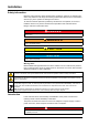
Installation Safety information Read the entire instruction sheet carefully before unpacking, setting up or operating this device. Pay attention to all danger and warning statements. Failure to do so could result in serious injury to the operator or damage to the device. To make sure that the protection provided by this device is not impaired, do not use or install this device in any manner other than that specified in this instruction sheet.
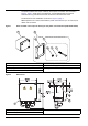
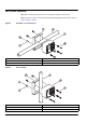
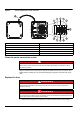
The parts included in the scope of delivery for the power connection box are listed in Figure 1, page 4. Under some circumstances, not all supplied parts are required. Therefore the only parts listed are those mentioned in this instruction sheet. The dimensions of the installation are shown in Figure 2, page 4. Note: Important note: Leave underneath the power connection box (i.e. 50–100 mm) for cables and connectors. Figure 1 Parts included in the scope of delivery for the power connection box (LQV155.99.
Assembly DANGER Risk of electric shock. This device may only be connected to a single-phase power supply at 100–240 V~, which is protected with a 15 A fuse or a current breaker. DANGER Risk of electric shock. The wire connection of the power supply must always contain a 2-pin disconnect switch available on site. The disconnect switch must meet the applicable regulations.
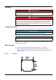
Rail or pole assembly Note: Make sure that the diameter of the rail or of the pole is between 35 and 55 mm. Note: Instructions on how to secure the housing with the clamping plate can be found in Figure 4, page 6 or Figure 5, page 6.
Electrical connections DANGER Risk of electric shock. For installation in wet areas or areas in which wetness can occur, a residual-current circuit breaker must always be installed with this socket. For assembly in outdoor areas, overvoltage protection is required. For fixed wire connections (cable conduit), a clearly labeled 2-pin disconnect switch must be installed on site next to the socket, in accordance with the applicable regulations.
3. Unscrew the nut of the strain relief (component 5). 4. Remove the cap of the strain relief (component 4). 5. Strip off the insulation of all three conductors of the power cable (phase, neutral conductor and earth conductor) over a length of 8 mm. The connection terminals are designed for solid or stranded conductors (18 – 16 AWG). 6. Feed the cables through the strain relief or cable guide.
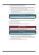
Figure 6 Cable connections 1 Cable guide 2 Sealing ring Note 3 Cable gland Observe the output voltage at the power sockets. The output voltage supplied by the power connection box to the power sockets corresponds to the country-specific mains voltage to which the power connection box is connected. Never connect consumers with a lower input voltage to the power connection box, if the power connection box is operated at a higher mains voltage.
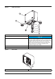
Figure 8 Circuit diagram (see inside of the lid) 1 Phase, line (live) 7 Black for left power socket 2 Connection to terminal 1 via bridge 8 Black for right power socket 3 Connection to terminal 4 via bridge 9 White for left power socket 4 Neutral conductor 10 White for right power socket 5 Protective ground (two terminals) 11 Fuse, T 5 A H, 250 V (4x) 6 Protective ground for left and right power socket 12 Lid protective ground Clean the power connection socket DANGER Risk of electric
2. Loosen the screws and remove the lid. 3. Open the fuse holder (there are two fuses for each analyzer connection: one for the phase and another for the neutral conductor — refer to Figure 7, page 9) and replace damaged fuses with fuses of the same type and with the same nominal values (T 5 A, time-lag, H, 250 V). Close the fuse holder (component 11, Figure 8, page 10). 4. Position the lid again and tighten the screws. Connect the sc analyzer DANGER Risk of electric shock.
Technical data Subject to change.
Warranty and liability The manufacturer warrants that the product supplied is free of material and manufacturing defects and undertakes the obligation to repair or replace any defective parts at zero cost. The warranty period for instruments is 24 months. If a service contract is taken out within 6 months of purchase, the warranty period is extended to 60 months.
Contact Information HACH Company World Headquarters P.O. Box 389 Loveland, Colorado 80539-0389 U.S.A. Tel (800) 227-HACH (800) -227-4224 (U.S.A. only) Fax (970) 669-2932 orders@hach.com www.hach.com Repair Service in the United States: HACH Company Ames Service 100 Dayton Avenue Ames, Iowa 50010 Tel (800) 227-4224 (U.S.A. only) Fax (515) 232-3835 Repair Service in Canada: Hach Sales & Service Canada Ltd.