
Manual

11
2. Loosen the screws and remove the lid.
3. Open the fuse holder (there are two fuses for each analyzer connection: one for the
phase and another for the neutral conductor — refer to Figure 7, page 9) and replace
damaged fuses with fuses of the same type and with the same nominal values (T
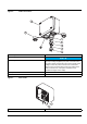
5 A, time-lag, H, 250 V). Close the fuse holder (component 11, Figure 8, page 10).
4. Position the lid again and tighten the screws.
Connect the sc analyzer
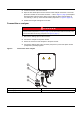
1. Remove the sealing cap from the connector.
2. Connect the analyzer to the power socket.
3. Secure the connector of the analyzer to the power socket.
4. Connect the sealing caps of the connector (component 1) and of the power socket
(component 2) securely together.
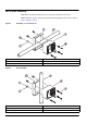
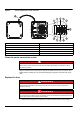
Figure 9 Connections of the analyzer
DANGER
Risk of electric shock.
If a power socket (component 4 in Figure 9, page 11) is not to be used, make sure that the power
socket is well sealed with the cap (component 2 in Figure 9, page 11).
1 Sealing cap for the analyzer connector 3 Analyzer connector
2 Sealing cap for the power socket 4 Power socket of the analyzer