DOC023.52.90448 RTC103 N-Module Real-Time Control System for Ammonium Removal User manual 07/2013, Edition 1A © HACH-LANGE GmbH 2013. All rights reserved. Printed in Germany.
Table of Contents Section 1 Technical data ........................................................................................................................ 7 Section 2 General Information............................................................................................................... 9 2.1 Safety information............................................................................................................................... 9 2.1.1 Use of hazard information....................
Table of Contents 4.9 Explanations of nitrification controller parameters.............................................................................47 4.9.1 SRT MODE ..............................................................................................................................47 4.9.2 SRT (MANUALLY) ...................................................................................................................48 4.9.3 DAILY SURPLUS MASS....................................................
Table of Contents 4.13 Volume............................................................................................................................................ 51 4.13.1 Aerated volume...................................................................................................................... 51 4.14 MODBUS ........................................................................................................................................ 51 4.14.1 ADDRESS..............................
Table of Contents 6
Section 1 Technical data These are subject to change without notice.
Technical data Analog output Outputs for DO setpoint or VFD control Number of outputs One-channel: 1 (KL4011); 1 (KL4012) VFD control Two-channel: 1 (KL4012); 2 (KL4012) VFD control Supply voltage 24 V DC via the power contacts (Alternatively, 15 V DC with bus termination KL9515) Signal current 0/4 to 20 mA Working resistance < 500 Ohm Measurement error ± 0.5 LSB linearity error ± 0.5 LSB offset error ± 0.
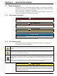
Section 2 2.1 General Information Safety information Please read this entire manual before unpacking, setting up, or operating this equipment. Pay attention to all danger and caution statements. Failure to do so could result in serious injury to the operator or damage to the equipment. To prevent damage to or impairment of the device's protection equipment, the device may only be used or installed as described in this manual. 2.1.
General Information 2.2 Areas of application The RTC103 N-Module is an universally applicable control unit which optimizes nitrification processes in wastewater treatment plants. In addition, the RTC103 N-Module can optionally be equipped with a closed-loop controller for setting the dissolved oxygen concentration (O2) in the activated sludge tank. The single-channel version of the RTC module controls one activated sludge tank. The two-channel version controls two activated sludge tanks simultaneously.
General Information 2.4 Instrument overview Figure 1 Base module RTC 100-240 V version 1 L(+) 7 Automatic circuit breaker (ON/OFF switch for item 10 and 11 without fuse function) 2 N(–) 8 sc 1000 connection: RS485 (CX1010-N041) 3 Input AVC 100–240 V / Input DC 95–250 V 9 Battery compartment 4 PE (protective earth) 10 CPU base module, consisting of Ethernet port with battery compartment (CX1010-N000), CPU module with CF card (CX1010-0021) and passive aeration element.
General Information Figure 2 Design of the analog and digital input and output modules 1 2 1 Analog or digital input or output module or bus termination module 2 LED area with installed LEDs or free LED installation spaces. Note: The number of LEDs indicates the number of channels. 2.5 2.5.
General Information Figure 3 Principle operation mode of RTC103 N-Module Basic RTC103 N-Module For each lane the calculated DO set point is delivered either by analog output or via the sc1000 ProfiBus communication card to the PLC. The DO control algorithm has to be implemented on the PLC. Option 2: RTC103 N-Module with DO aeration stages controller The RTC103 N-Module is equipped with an additional DO controller adjusting the aeration intensity to reach the calculated DO concentration.
General Information 14
Section 3 Installation DANGER Only qualified experts may perform the tasks described in this section of the manual, while adhering to all locally valid safety regulations. CAUTION Always lay cables and hoses so that they are straight and do not pose a tripping hazard. CAUTION Before switching on the power supply, you must refer to the instructions in the relevant operating manuals. 3.1 Installation of the RTC Module Only install the RTC Module on a DIN rail.
Installation 3.3 Connecting the sc 1000 controller The supplied SUB-D connector is attached to a two-wire, shielded data cable (signal or bus cable). For additional information regarding the data cable connection, refer to the enclosed assembly instructions. 3.
Installation 1-Channel RTC103 N-Module Module Name Terminal Signal 2 fold digital output1 KL2032 1 fold analog output 1 fold analog intput 1 +24 V/0 V Input Signals ok (24V), Input signal faulty (0V) 5 +24 V/0 V RTC operating (24V), RTC failure (0V) KL4011 1-3 0/4 to 20 mA Output DO set point KL3011 1-2 0/4 to 20 mA Flow rate aeration lane 1 fold analog input KL3011 1-2 0/4 to 20 mA Flow rate internal recirculation or return sludge Bus termination KL9010 1 Ground Channel Functi
Installation 2-Channel RTC103 N-Module DO aeration stages control Module Name 16 fold digital output1 KL2809 Terminal Signal Channel Function 1 +24 V/0 V 1 Input Signals ok (24V), Input signal faulty (0V) 2 +24 V/0 V 1 Aeration step 1 ON / OFF 3 +24 V/0 V 1 Aeration step 2 ON / OFF 4 +24 V/0 V 1 Aeration step 3 ON / OFF 5 +24 V/0 V 1 Aeration step 4 ON / OFF 6 +24 V/0 V 1 Aeration step 5 ON / OFF 7 +24 V/0 V Aeration step 6 ON / OFF 8 +24 V/0 V RTC Channel 1 operating (2
Installation 2-Channel RTC103 N-Module connectors DO aeration stages / analog control Module Name 16 fold digital output1 KL2809 Terminal Signal Channel Function 1 +24 V/0 V 1 Input Signals ok (24V), Input signal faulty (0V) 2 +24 V/0 V 1 Aeration step 1 ON / OFF (VFD) 3 +24 V/0 V 1 Aeration step 2 ON / OFF (VFD) 4 +24 V/0 V 1 Aeration step 3 ON / OFF 5 +24 V/0 V 1 Aeration step 4 ON / OFF 6 +24 V/0 V 1 Aeration step 5 ON / OFF 7 +24 V/0 V 1 Aeration step 6 ON / OFF 8 +2
Installation 20
Section 4 4.1 Parameterization and operation Operating the sc controller The RTC module can only be operated using the sc1000 controller, in conjunction with the RTC communication card. Before the RTC module is used, the user must be familiar with the functionality of the sc1000 controller. Learn how to navigate through the menu and perform the relevant functions. 4.2 System setup 1. Open the MAIN MENU. 2. Select RTC MODULES / PROGNOSYS and confirm. 3. Select the RTC MODULES menu and confirm. 4.
Parameterization and operation 4.4.1 1-Channel RTC103 N-Module RTC MODULES / PROGNOSYS RTC MODULES RTC CONFIGURE SELECT SENSOR Selection list of available, relevant sensors for the RTC module in the sc network (refer to 4.6 Select sensors on page 45).
Parameterization and operation 4.4.1 1-Channel RTC103 N-Module (Continued) RTC MODULES / PROGNOSYS RTC MODULES RTC Note: These settings are only necessary if NH4-N measurement in effluent for feed back control is available! P FACT NH4 [1/mg/L] Proportional factor for the PID closed loop controller for the NH4-N concentration effluent aeration.
Parameterization and operation 4.4.1 1-Channel RTC103 N-Module (Continued) RTC MODULES / PROGNOSYS RTC MODULES RTC Note: 0/4 to20 mA input can be used either for Qreci or for Qras. MIN RECIRCULATION Minimum recirculation flow rate according to measurement signal corresponding to 0/4mA [L/s] Note: 0/4 to20 mA input can be used either for Qreci or for Qras.
Parameterization and operation 4.4.1 1-Channel RTC103 N-Module (Continued) RTC MODULES / PROGNOSYS RTC MODULES RTC OUTPUTS MIN DO SETTING Minimum DO set point corresponding to 0/4mA [mg/L] MAX DO SETTING Maximum DO set point corresponding to 20mA [mg/L] 0/4 to 20 mA Transfer range of 0/4 to 20 mA current loop as set in connected flow measuring instrument. VOLUME VOLUME Aerated volume [m3] MODBUS ADDRESS Start address of an RTC within the MODBUS network.
Parameterization and operation 4.4.2 1-Channel RTC103 N-Module Stages RTC MODULES / PROGNOSYS RTC MODULES RTC CONFIGURE SELECT SENSOR Selection list of available, relevant sensors for the RTC module in the sc network (refer to 4.6 Select sensors on page 45).
Parameterization and operation 4.4.2 1-Channel RTC103 N-Module Stages (Continued) RTC MODULES / PROGNOSYS RTC MODULES RTC MODEL CORRECTION FACT. This factor can be used on order to fine tune the DO concentration calculated by the model (feed forward part of the N-RTC). SUBSTIT.
Parameterization and operation 4.4.2 1-Channel RTC103 N-Module Stages (Continued) RTC MODULES / PROGNOSYS RTC MODULES RTC Note: 0/4 to20 mA input can be used either for Qreci or for Qras. MIN RECIRCULATION Minimum recirculation flow rate according to measurement signal corresponding to 0/4mA [L/s] Note: 0/4 to20 mA input can be used either for Qreci or for Qras.
Parameterization and operation 4.4.3 1-Channel RTC103 N-Module VFD RTC MODULES / PROGNOSYS RTC MODULES RTC CONFIGURE SELECT SENSOR Selection list of available, relevant sensors for the RTC module in the sc network (refer to 4.6 Select sensors on page 45).
Parameterization and operation 4.4.3 1-Channel RTC103 N-Module VFD (Continued) RTC MODULES / PROGNOSYS RTC MODULES RTC Note: These settings are only necessary if NH4-N measurement in effluent for feed back control is available! P FACT NH4 [1/mg/L] Proportional factor for the PID closed loop controller for the NH4-N concentration effluent aeration.
Parameterization and operation 4.4.3 1-Channel RTC103 N-Module VFD (Continued) RTC MODULES / PROGNOSYS RTC MODULES RTC Note: 0/4 to20 mA input can be used either for Qreci or for Qras. MIN RECIRCULATION Minimum recirculation flow rate according to measurement signal corresponding to 0/4mA [L/s] Note: 0/4 to20 mA input can be used either for Qreci or for Qras.
Parameterization and operation 4.4.3 1-Channel RTC103 N-Module VFD (Continued) RTC MODULES / PROGNOSYS RTC MODULES RTC MODBUS ADDRESS Start address of an RTC within the MODBUS network. DATA ORDER Specifies the register order within a double word. Presetting: NORMAL DATALOG INTRVAL Indicates the interval in which the data is saved in the log file. PROGNOSYS Activate or deactivate PROGNOSYS for RTC control.
Parameterization and operation 4.5.1 2-Channel RTC103 N-Module RTC MODULES / PROGNOSYS RTC MODULES RTC CONFIGURE SELECT SENSOR Selection list of available, relevant sensors for the RTC module in the sc network (refer to 4.6 Select sensors on page 45).
Parameterization and operation 4.5.1 2-Channel RTC103 N-Module (Continued) RTC MODULES / PROGNOSYS RTC MODULES RTC MODEL CORRECTION FACT. This factor can be used to fine tune the DO concentration calculated by the model (feed forward part of the N-RTC). SUBSTIT. DO FOR MODEL If there is a failure in any of the input signals (NH4-N, TSS, Flow) the N-RTC will apply this DO feed forward set point for all further calculations.
Parameterization and operation 4.5.1 2-Channel RTC103 N-Module (Continued) RTC MODULES / PROGNOSYS RTC MODULES RTC Note: 0/4 to20 mA input can be used either for Qreci or for Qras. MIN RECIRCULATION Minimum recirculation flow rate according to measurement signal corresponding to 0/4mA [L/s] Note: 0/4 to20 mA input can be used either for Qreci or for Qras.
Parameterization and operation 4.5.1 2-Channel RTC103 N-Module (Continued) RTC MODULES / PROGNOSYS RTC MODULES RTC OUTPUTS CHANNEL 1 MIN DO SETTING Minimum DO set point corresponding to 0/4mA [mg/L] MAX DO SETTING Maximum DO set point corresponding to 20mA [mg/L] 0/4 to 20 mA Transfer range of 0/4 to 20 mA current loop as set in connected flow measuring instrument.
Parameterization and operation 4.5.2 2-Channel RTC103 N-Module Stages RTC MODULES / PROGNOSYS RTC MODULES RTC CONFIGURE SELECT SENSOR Selection list of available, relevant sensors for the RTC module in the sc network (refer to 4.6 Select sensors on page 45).
Parameterization and operation 4.5.2 2-Channel RTC103 N-Module Stages (Continued) RTC MODULES / PROGNOSYS RTC MODULES RTC MODEL CORRECTION FACT. This factor can be used on order to fine tune the DO concentration calculated by the model (feed forward part of the N-RTC). SUBSTIT.
Parameterization and operation 4.5.2 2-Channel RTC103 N-Module Stages (Continued) RTC MODULES / PROGNOSYS RTC MODULES RTC INPUTS CHANNEL 1 MIN INFLOW Minimum flow rate of influent according to measurement signal corresponding to 0/4mA [L/s] MAX INFLOW Maximum flow rate of influent according to measurement signal corresponding to 20mA [L/s] 0/4 to 20 mA Transfer range of 0/4 to 20 mA current loop as set in connected flow measuring instrument.
Parameterization and operation 4.5.2 2-Channel RTC103 N-Module Stages (Continued) RTC MODULES / PROGNOSYS RTC MODULES RTC Note: 0/4 to20 mA input can be used either for Qreci or for Qras. Q RETURN RATIO CHANNEL 2 If the value Q RETURN RATIO is “0” the RAS flow is calculated bases on the mA input signal. If the value is different from “0” the RAS flow is calculated from the inflow: Q RETURN = Q RETURN RATIO * INFLOW within the limits of MIN RETURN SLUDGE and MAX RETURN SLUDGE.
Parameterization and operation 4.5.3 2-Channel RTC103 N-Module VFD (Continued) RTC MODULES / PROGNOSYS RTC MODULES RTC SRT MODE Three different types of operation regarding the aerobic Sludge Retention Time (SRT) can be selected: • Manually: The SRT is provided as a manual input to the controller • SRT-RTC: The SRT is provided by a separate SRT-RTC and forwarded to the RTC103 N-Module • TSS mL: The SRT is calculated based on the TSS concentration and the amount of TSS daily removed.
Parameterization and operation 4.5.3 2-Channel RTC103 N-Module VFD (Continued) RTC MODULES / PROGNOSYS RTC MODULES RTC MODEL CORRECTION FACT. This factor can be used on order to fine tune the DO concentration calculated by the model (feed forward part of the N-RTC). SUBSTIT.
Parameterization and operation 4.5.3 2-Channel RTC103 N-Module VFD (Continued) RTC MODULES / PROGNOSYS RTC MODULES RTC INPUTS CHANNEL 1 MIN INFLOW Minimum flow rate of influent according to measurement signal corresponding to 0/4mA [L/s] MAX INFLOW Maximum flow rate of influent according to measurement signal corresponding to 20mA [L/s] 0/4 to 20 mA Transfer range of 0/4 to 20 mA current loop as set in connected flow measuring instrument.
Parameterization and operation 4.5.3 2-Channel RTC103 N-Module VFD (Continued) RTC MODULES / PROGNOSYS RTC MODULES RTC Note: 0/4 to20 mA input can be used either for Qreci or for Qras. Q RETURN RATIO CHANNEL 2 If the value Q RETURN RATIO is “0” the RAS flow is calculated bases on the mA input signal. If the value is different from “0” the RAS flow is calculated from the inflow: Q RETURN = Q RETURN RATIO * INFLOW within the limits of MIN RETURN SLUDGE and MAX RETURN SLUDGE.
Parameterization and operation 4.5.3 2-Channel RTC103 N-Module VFD (Continued) RTC MODULES / PROGNOSYS RTC MODULES RTC 4.6 SOFT-VERSION Shows the software version of the RTC communication card (YAB117) in the sc1000. RTC MODE Shows the installed RTC module variant, e.g. 1-channel closed-loop control. RTC VERSION Shows the software version of the RTC module. Select sensors 1. To select sensors and their sequence for the RTC module, press RTC > CONFIGURE > SELECT SENSOR.
Parameterization and operation 3. Press the required sensor for the RTC module and confirm by pressing ENTER below the selection list. Sensors in black type are available for the RTC module. Sensors in red type are not available for the RTC module. Note: For sensors marked (p), PROGNOSYS is available if these sensors have been selected in conjunction with an RTC module (refer to the PROGNOSYS user manual). 4. The selected sensor is shown in the sensor list.
Parameterization and operation 7. Press ENTER (Figure 4, item 1) to confirm the list once it is finished. Note: The order of selected sensors has to be defined and pre-configured by Service of Supplier on CF-card of RTC103 N-Module. 4.7 Control programs To adapt to local circumstances and the instruments available, there are 4 different programs available for calculating desired DO concentration for nitrification The choice of program depends on the available measurement signals.
Parameterization and operation 4.9.2 SRT (MANUALLY) Manual input for the Sludge Retention Time (SRT [d]). In case of a failing TSS signal, this is also used as fallback value. 4.9.3 DAILY SURPLUS MASS The amount of sludge daily removed from the process. Based on that amount, the MLSS concentration in the aeration tank and the aerated volume the SRT is calculated. 4.9.4 COD-TKN RATIO This is the assumed COD / TKN ratio.
Parameterization and operation 4.9.11 INTEGRAL TIME NH4 (only if NH4-N measurement in effluent is available for feed back control) Integral time for the PID closed loop controller for the NH4-N concentration in the thickened sludge. Note: INTEGRAL TIME NH4 is set to “0” to deactivate the integral part of the PID controller. 4.9.
Parameterization and operation 4.10.5 SUBST AERATION If the oxygen sensor (e.g. LDO) signals a fault, the set aeration stage is selected (stages 1 to 6). 4.10.6 NUMBER OF STAGES Number of controlled aeration stages (maximum 6). 4.10.7 VFD P MIN (For DO control without VFD option this is fixed to 100%) Set minimum speed [%] for VFD controlled blowers. 4.11 INPUTS There are available two mA input connector for each channel. The first is the flowrate signal (inlet or effluent of plant or lane).
Parameterization and operation 4.11.8 MIN RETURN SLUDGE Minimum return sludge flow rate according to measurement signal corresponding to 0/4mA. 4.11.9 MAX RETURN SLUDGE Maximum return sludge flow rate of influent according to measurement signal corresponding to 20mA. 4.11.10 0/4 to 20mA Transfer range of 0/4 to 20mA current loop as set in connected flow measuring instrument. 4.11.11 Q RETURN RATIO If the value Q RETURN RATIO is “0” the RAS flow is calculated bases on the mA input signal.
Parameterization and operation 4.15 Displayed measurement values and variables The following measurement values and variables are shown on the SC1000 display and transferred via fieldbus.
Section 5 5.1 Maintenance Maintenance schedule DANGER Multiple hazards Only qualified personnel must conduct the tasks described in this section of the manual.
Maintenance 54
Section 6 6.1 Troubleshooting Error messages Possible RTC errors are displayed by the sc controller.
Troubleshooting 56
Section 7 7.1 Replacement parts and accessories Replacement Parts Description Cat. No DIN rail NS 35/15, punched according to DIN EN 60715 TH35, made of galvanized steel. Length: 35 cm (13.78 in.) LZH165 Transformer 90–240 V AC/24 V DC 0.75 A, module for top hat rail assembly LZH166 Terminal for 24 V connection without power supply LZH167 Grounding terminal LZH168 SUB-D connector LZH169 C2 circuit breaker LZH170 CPU base module with Ethernet port, passive ventilation element.
Replacement parts and accessories 58
Section 8 Contact information HACH Company World Headquarters P.O. Box 389 Loveland, Colorado 80539-0389 U.S.A. Tel (800) 227-HACH (800) -227-4224 (U.S.A. only) Fax (970) 669-2932 orders@hach.com www.hach.com Repair Service in the United States: HACH Company Ames Service 100 Dayton Avenue Ames, Iowa 50010 Tel (800) 227-4224 (U.S.A. only) Fax (515) 232-3835 Repair Service in Canada: Hach Sales & Service Canada Ltd.
Contact information HACH LANGE D.O.O. Fajfarjeva 15 SI-1230 Domžale Tel. +386 (0)59 051 000 Fax +386 (0)59 051 010 info@hach-lange.si www.hach-lange.si HACH LANGE OOO Finlyandsky prospekt, 4A Business Zentrum “Petrovsky fort”, R.803 RU-194044, Sankt-Petersburg Tel. +7 (812) 458 56 00 Fax. +7 (812) 458 56 00 info.russia@hach-lange.com www.hach-lange.com 60 ΗΑCH LANGE E.Π.Ε. Ηρακλείτου 3 GR-15235 Χαλάνδρι Τηλ. +30 210 7777038 Fax +30 210 7777976 info@hach-lange.gr www.hach-lange.
Section 9 Warranty and liability The manufacturer warrants that the supplied product is free of material and manufacturing defects, and undertakes to repair or to replace any defective parts without charge. The warranty period is 24 months. If a maintenance contract is taken out within 6 months of purchase, the warranty period is extended to 60 months.
Warranty and liability 62
Appendix A MODBUS address setting The same slave address must be set for Modbus communication both on the sc1000 controller display and on the RTC103 N-Module. Since 20 slave numbers are reserved for internal purposes, the following numbers are available for assignment: 1, 21, 41, 61, 81, 101… The start address 41 is preset at the factory.
MODBUS address setting 64
Index A Address setting ........................................................ 63 Aeration element ...................................................... 11 B Base module ............................................................ 11 Battery compartment ................................................ 11 Bus coupler .............................................................. 11 Module Base ...................................................................... 11 Bus termination .....................
Index 66