
Manual


11
General Information
2.4 Instrument overview
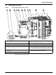
Figure 1 Base module RTC 100-240 V version
Note: All components are pre-wired.
1 L(+) 7 Automatic circuit breaker (ON/OFF switch for item 10
and 11 without fuse function)
2 N(–) 8 sc 1000 connection: RS485 (CX1010-N041)
3 Input AVC 100–240 V / Input DC 95–250 V 9 Battery compartment
4 PE (protective earth) 10 CPU base module, consisting of Ethernet port with
battery compartment (CX1010-N000), CPU module with
CF card (CX1010-0021) and passive aeration element.
5 24 V transformer (Specifications refer section 3.1.1,
page 15)
11 Power supply module, consisting of bus coupler
(CX1100-0002) and terminal module 24V.
6 Output DC 24 V, 0.75 A