
Manual


19
Installation
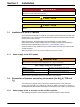
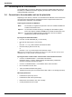
2-Channel RTC103 N-Module connectors DO aeration stages / analog control
Module Name Terminal Signal Channel Function
16 fold digital output
1
KL2809
1 +24 V/0 V 1 Input Signals ok (24V), Input signal faulty (0V)
2 +24 V/0 V 1 Aeration step 1 ON / OFF (VFD)
3 +24 V/0 V 1 Aeration step 2 ON / OFF (VFD)
4 +24 V/0 V 1 Aeration step 3 ON / OFF
5 +24 V/0 V 1 Aeration step 4 ON / OFF
6 +24 V/0 V 1 Aeration step 5 ON / OFF
7 +24 V/0 V 1 Aeration step 6 ON / OFF
8 +24 V/0 V 1 RTC Channel 1 operating (24V), RTC failure (0V)
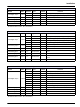
9 +24 V/0 V 2 Input Signals ok (24V), Input signal faulty (0V)
10 +24 V/0 V 2 Aeration step 1 ON / OFF (VFD)
11 +24 V/0 V 2 Aeration step 2 ON / OFF (VFD)
12 +24 V/0 V 2 Aeration step 3 ON / OFF
13 +24 V/0 V 2 Aeration step 4 ON / OFF
14 +24 V/0 V 2 Aeration step 5 ON / OFF
15 +24 V/0 V 2 Aeration step 6 ON / OFF
16 +24 V/0 V 2 RTC Channel 2 operating (24V), RTC failure (0V)
2 fold analog output KL4012
0/4 to 20 mA 1 Output 1 VFD for DO control
0/4 to 20 mA 1 Output 2 VFD for DO control
2 fold analog output KL4012
0/4 to 20 mA 2 Output 1 VFD for DO control
0/4 to 20 mA 2 Output 2 VFD for DO control
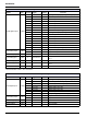
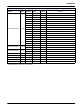
1 fold analog intput KL3011 1 - 2 0/4 to 20 mA 1 Flow rate aeration lane
1 fold analog input KL3011 1 - 2 0/4 to 20 mA 1 Flow rate internal recirculation
1 fold analog intput KL3011 1 - 2 0/4 to 20 mA 2 Flow rate aeration lane
1 fold analog input KL3011 1 - 2 0/4 to 20 mA 2 Flow rate internal recirculation
Bus termination KL9010 Bus termination
1
Ground Connector 3 and 7, 24 V Connector 6.