DOC023.52.90386 RTC113 ST-Module Real Time Controller – Sludge Thickening-Module User manual 12/2012, Edition 2A © HACH-LANGE GmbH, 2012. All rights reserved. Printed in Germany.
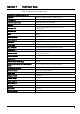
Table of contents Section 1 Technical data .......................................................................................................................... 7 Section 2 General information .................................................................................................................. 9 2.1 Safety information............................................................................................................................... 9 2.1.1 Hazard notices in this manual..........
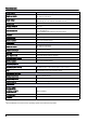
Table of contents 4.7 CONTROL PARAMETER .................................................................................................................28 4.7.1 FACTOR POLYMER DOSING.................................................................................................28 4.7.2 POLYMER CONCENTRATION ...............................................................................................28 4.7.3 MANUAL POLYMER DOSING............................................................................
Table of contents Section 6 Troubleshooting ...................................................................................................................... 37 6.1 Error messages ................................................................................................................................ 37 6.2 Warnings........................................................................................................................................... 37 6.3 Wear parts .........................
Table of contents 6
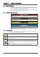
Section 1 Technical data These are subject to change without notice.
Technical data Analog outputs Output of the polymer dosing, output of the feed flow rate Number of outputs One-channel: 2 (KL4012) Two-channel: 4 (KL4012) Supply voltage 24 V DC via the power contacts (Alternatively, 15 V DC with bus termination KL9515) Signal current 0/4 to 20 mA Working resistance <500 ohm Measurement error ± 0.5 LSB linearity error ± 0.5 LSB offset error ± 0.1 % (relative to the measuring range end value) Resolution 12 bit Conversion time Approximately 1.
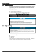
Section 2 2.1 General information Safety information Please read the entire manual carefully before unpacking, assembling or operating the instrument. Pay attention to all hazard and warning notices. Failure to do so could result in serious injury to the operator or damage to the instrument. To prevent damage to or impairment of the device's protection equipment, the device may only be used or installed as described in this manual. 2.1.
General information 2.2 Areas of application The RTC113 ST-Module (Real Time Controller, Sludge Thickening-Module) is an open and closed-loop control unit for universal applications. It can be used by mechanical sludge thickening devices, for example belt thickeners or drum thickeners in wastewater treatment plants.
General information 2.4 Instrument overview Figure 1 Base module RTC 24 V version . 1 PE (protective earth) 5 sc 1000 connection: RS485 (CX1010-N031) 2 24 V 6 Battery compartment 3 0V 7 CPU base module, consisting of Ethernet port with battery compartment (CX1010-N000), CPU module with CF card (CX1010-0021) and passive aeration element. 4 Automatic circuit breaker (ON/OFF switch for item 7 and 8 without fuse function).
General information Abbildung 2 Base module RTC 100-240 V version 1 L(+) 7 Automatic circuit breaker (ON/OFF switch for item 10 and 11 without fuse function). 2 N(–) 8 sc 1000 connection: RS485 (CX1010-N041) 3 Input AC 100–240 V / Input DC 95 V–250 V 9 Battery compartment 4 PE (protective earth) 10 CPU base module, consisting of Ethernet port with battery compartment (CX1010-N000), CPU module with CF card (CX1010-0021) and passive aeration element.
General information Figure 3 Design of the analog and digital input and output modules 1 2 1 Input- or Output- Module or Bus Termination Module analog or digital 2 LED area with installed LEDs or free LED installation spaces Note: The number of LEDs indicates the number of channels. 2.5 2.5.
General information 2.5.4 Operating modes The RTC113 ST-Module can be operated as a combined open-loop and closed-loop controller. Several variants can be configured. 1. Configuration of a specified polymer rate [L/h] with a specified feed flow rate [m3/h]. 2. Configuration of a specified specific polymer dosing rate [g polymer/kg TSS]. One of the following settings is adjusted: a. The polymer flow rate according to the TSS concentration and the feed flow rate (Figure 4).
General information Figure 4 Adjustment of the polymer dosing rate to the feed flow rate 1 Static thickener 8 Pump for open-loop control of the polymer dosing rate 2 Measurement of the feed flow rate 9 Pump for the feed flow rate 3 Open-loop control of the polymer dosing rate (feed flow rate measurement value) 10 Mechanical sludge thickener 4 TSS measurement from the influent 11 TSS measurement in the thickened sludge outlet 5 Open-loop control of the polymer dosing rate (influent TSS conce
General information Figure 5 Adjustment of the feed flow rate to the specified polymer dosing rate 1 Static thickener 8 Pump for polymer dosing: constant here 2 Influent 9 Mechanical sludge thickener 3 TSS measurement from the influent 10 TSS measurement in the thickened sludge outlet 4 Open-loop control for the feed flow rate 11 Closed-loop control for the feed flow rate 5 RTC113 ST-Module 12 Thickened sludge pump 6 Pump for open-loop control of the feed flow rate 13 Digester 7 Polym
Section 3 Installation DANGER Only qualified experts may perform the tasks described in this section of the manual, while adhering to all locally valid safety regulations. CAUTION Always lay cables and hoses so that they are straight and do not pose a tripping hazard. CAUTION Before the power supply is switched on, refer to the instructions in the relevant manuals. 3.1 Installation of the RTC Module Only install the RTC Module on a DIN rail.
Installation 3.4 Connection to the automation unit on the plant side The one-channel and two-channel versions of the ST-Module are equipped with various modules that must be connected to the plant automation system. • The feed flow rate must be provided to the ST-Module as a 0/4 to 20 mA signal. • The polymer flow rate must be provided (on both versions) to the ST-Module as a 0/4 to 20 mA signal. • The status signal of the thickened sludge pump (on/off) must be a digital input signal (24 V/0 V).
Installation Table 4 Connections for the 2-channel RTC113 ST-Module Module Name 8x digital output1 2x analog output KL2408 KL4012 Connection Signal Channel Function 1 +24 V/0 V 1 Polymer pump on/off (24 V/0 V) 5 +24 V/0 V 1 Closed-loop control of the feed flow rate active/inactive (24 V/0 V) 2 +24 V/0 V 1 Input signals OK (24 V), input signal faulty (0 V) 6 +24 V/0 V 1 RTC operational (24 V), RTC faulty (0 V) 3 +24 V/0 V 2 Polymer pump on/off (24 V/0 V) 7 +24 V/0 V 2 Closed-l
Installation 20
Section 4 4.1 Parameterization and operation Operating the sc controller The RTC Module can only be operated via the sc1000 controller in conjunction with the RTC communication card. Before the RTC Module is used, the user must be familiar with the functionality of the sc1000 controller. Learn how to navigate through the menu and perform the relevant functions. 4.2 sc1000 setup 1. Open the MAIN MENU. 2. Select RTC MODULES / PROGNOSYS and confirm. 3. Select RTC MODULES and confirm. 4.
Parameterization and operation 4.4.1 RTC113 ST-Module open and closed-loop controller (Continued) RTC MODULES / PROGNOSYS RTC MODULES RTC PRESELECT PROG. CHANNEL 1 POLYMER DOSING CONTROL Based on the feed flow rate [m³/h] and measured TSS concentration [g/L] from the influent, the polymer dosing rate [L/h] is calculated such that it corresponds to the target specific polymer dosing rate [g/kg].
Parameterization and operation 4.4.1 RTC113 ST-Module open and closed-loop controller (Continued) RTC MODULES / PROGNOSYS RTC MODULES RTC CONTROL PARAMETER CHANNEL 1 FACTOR POLYMER DOSING Required specific polymer dosing [g/kg]. This parameter determines how many grams of polymer per kilogram of TSS are fed by the machine. g/kg POLYMER CONCENTRATION Polymer concentration [g/L] fed via the polymer pump.
Parameterization and operation 4.4.1 RTC113 ST-Module open and closed-loop controller (Continued) RTC MODULES / PROGNOSYS RTC MODULES RTC INPUT/OUTPUT LIMITS CHANNEL 1 FEED FLOW LOW Feed flow rate input signals below this value [m3/h] are set to this value (to avoid low flow peaks). m3/h FEED FLOW HIGH Feed flow rate input signals above this value [m3/h] are set to this value (to avoid high flow peaks). m3/h FEED FLOW SMOOTHING Feed flow measurement values are smoothed in line with this parameter.
Parameterization and operation 4.4.1 RTC113 ST-Module open and closed-loop controller (Continued) RTC MODULES / PROGNOSYS RTC MODULES RTC OUTPUTS CHANNEL 1 MIN FEED FLOW Minimum feed flow rate [m³/h] in accordance with 0/4 mA. m³/h MAX FEED FLOW Maximum feed flow rate [m³/h] in accordance with 20 mA. m³/h 0/4...20mA Transfer range of 0/4 to 20 mA current loop (as set on connected flow measuring instrument). MIN POLYMER FLOW Minimum polymer pump delivery rate in accordance with 0/4 mA.
Parameterization and operation 4.5 Select sensors 1. To select sensors and their sequence for the RTC Module, press RTC > CONFIGURE > SELECT SENSOR. Figure 6 Select sensor 1 ENTER — Saves the setting and returns to the CONFIGURE menu. 4 DELETE — Removes a sensor from the selection. 2 CANCEL — Returns to the CONFIGURE menu without saving. 5 UP/DOWN — Moves the sensors up or down. 3 ADD — Adds a new sensor to the selection. 2. Press ADD (Figure 6, item 3).
Parameterization and operation 4. The selected sensor is shown in the sensor list. Press ADD (Figure 6, item 3) to open the selection list again. 5. Select the second sensor for the RTC Module and confirm by pressing ENTER below the selection list. Note: Previously selected sensors are shown in gray. The selected sensors are shown in the sensor list. 6. To sort the sensors in the order specified for the RTC Module, press the sensor and use the arrow keys to move it (Figure 6, item 5).
Parameterization and operation 4.6 4.6.1 PRESELECT PROG POLYMER DOSING CONTROL Based on the measured feed flow rate [m³/h] and the measured TSS concentration [g/L] from the influent, the polymer dosing rate [L/h] is calculated such that the setpoint corresponds to the specific polymer dosing rate [g/kg]. Note: This open-loop control mode can only be activated if FEED FLOW CONTROL is deactivated. Note: The polymer flow rate is controlled via the RTC. 4.6.
Parameterization and operation 4.7.3 MANUAL POLYMER DOSING The RTC outputs the polymer dosing rate [L/h] if 4.7.4 • FEED FLOW CONTROL is activated • No open-loop control mode (section 4.6.1 to section 4.6.3) is activated • The TSS measurement from the influent reports an error, or • The flow measurement from the influent reports an error. MANUAL FEED FLOW The RTC outputs the feed flow rate [m3/h] if 4.7.5 • POLYMER DOSING CONTROL is activated • No open-loop control mode (section 4.6.
Parameterization and operation 4.7.10 DERIVATIVE TIME TSS Derivative time for the PID closed-loop controller for the TSS concentration in the thickened sludge. 4.8 4.8.1 INPUT/OUTPUT LIMITS FEED FLOW LOW Feed flow rate input signals below this value [m3/h] are set to this value. This means that very low feed flow rates can be avoided. 4.8.2 FEED FLOW HIGH Feed flow rate input signals above this value [m3/h] are set to this value. This avoids load peaks. 4.8.
Parameterization and operation 4.8.7 LIMIT TSS OUT LOW TSS measurement values for the thickened sludge that are below this value [g/L] are set to this value (to avoid low peaks). 4.8.8 LIMIT TSS OUT HIGH TSS measurement values for the thickened sludge that are above this value [m3/h] are set to this value (to avoid high peaks). 4.8.9 TSS OUT SMOOTHING TSS measurement values from the effluent are smoothed in line with this parameter. SMOOTHING = 1: The signal is not smoothed.
Parameterization and operation 4.9.4 MIN POLYMER FLOW Minimum polymer dosing in [L/h] in accordance with the 0/4 mA measurement signal. 4.9.5 MAX POLYMER FLOW Maximum polymer dosing in [L/h] in accordance with the 20 mA measurement signal. 4.9.6 0/4...20 mA Transfer range of the 0/4 to 20 mA current loop (as set in connected flow measuring instrument). 4.10 OUTPUTS 4.10.1 MIN FEED FLOW Minimum feed flow rate [m³/h] in accordance with 0/4 mA. 4.10.
Parameterization and operation 4.10.8 MIN RUNTIME Minimum ON time in pulse/pause dosing mode. The pump is activated for this runtime at the very least. The MIN RUNTIME must be shorter than the duration of the CONTROL CYCLE. 4.11 Displayed measurement values and variables The following measurement values and variables are shown on the sc1000 display and transferred via fieldbus (refer to section Appendix B).
Parameterization and operation 34
Section 5 Maintenance DANGER Multiple hazards Only qualified personnel must conduct the tasks described in this section of the manual. 5.
Maintenance 36
Section 6 6.1 Troubleshooting Error messages Possible RTC errors are displayed by the sc controller.
Troubleshooting 38
Section 7 7.1 Replacement parts and accessories Replacement parts Description Cat. No DIN rail NS 35/15, punched according to DIN EN 60715 TH35, made of galvanized steel. Length: 35 cm (13.78 in.) LZH165 Transformer 90–240 V AC/24 V DC 0.75 A, module for DIN rail assembly LZH166 Terminal for 24 V connection without power supply LZH167 Terminal for protective earth LZH168 SUB-D connector LZH169 C2 circuit breaker LZH170 CPU base module with Ethernet port, passive ventilation element.
Replacement parts and accessories 40
Section 8 Contact information Repair Service in the United States: HACH Company Ames Service 100 Dayton Avenue Ames, Iowa 50010 Tel (800) 227-4224 (U.S.A. only) Fax (515) 232-3835 Repair Service in Canada: Hach Sales & Service Canada Ltd. 1313 Border Street, Unit 34 Winnipeg, Manitoba R3H 0X4 Tel (800) 665-7635 (Canada only) Tel (204) 632-5598 Fax (204) 694-5134 canada@hach.
Contact information HACH LANGE D.O.O. Fajfarjeva 15 SI-1230 Domžale Tel. +386 (0)59 051 000 Fax +386 (0)59 051 010 info@hach-lange.si www.hach-lange.si HACH LANGE OOO Finlyandsky prospekt, 4A Business Zentrum “Petrovsky fort”, R.803 RU-194044, Sankt-Petersburg Tel. +7 (812) 458 56 00 Fax. +7 (812) 458 56 00 info.russia@hach-lange.com www.hach-lange.com 42 ΗΑCH LANGE E.Π.Ε. Αυλίδος 27 GR-115 27 Αθήνα Τηλ. +30 210 7777038 Fax +30 210 7777976 info@hach-lange.gr www.hach-lange.gr HACH LANGE D.O.O.
Section 9 Warranty and liability The manufacturer warrants that the supplied product is free of material and manufacturing defects, and undertakes to repair or to replace any defective parts without charge. The warranty period is 24 months. If a maintenance contract is taken out within 6 months of purchase, the warranty period is extended to 60 months.
Warranty and liability 44
Appendix A Modbus address setting The same slave address must be set for Modbus communication on the sc1000 controller display and in the RTC module. Since 20 slave numbers are reserved for internal purposes, the following numbers are available for assignment: 1, 21, 41, 61, 81, 101… The start address 41 is preset at the factory.
Modbus address setting 46
Appendix B Configuration of the network modules B.
Configuration of the network modules 48
Index Numerics 1-channel version ..................................................... 18 2-channel version ..................................................... 18 A Abmessungen .......................................................... 11 Address setting ........................................................ 45 aeration element ................................................ 11, 12 B Battery compartment .......................................... 11, 12 C Closed-loop controller behavior .............
Index 50