DOC023.52.90143.Jan09 sc1000 Controller Enhanced Communications MANUAL Edition 1 © HACH LANGE GmbH, 2009. All rights reserved.
Table of contents Section 1 Specifications ............................................................................................................................... 5 Section 2 General information ................................................................................................................... 7 2.1 Safety information .............................................................................................................................................. 7 2.
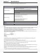
Section 1 Specifications Specifications are subject to change without notice. sc1000 controller display module The sc1000 display module with integrated GSM/GPRS modem transfers data, SMS and GPRS services to GSM networks. The sc1000 controller is available with various GSM frequencies: *GSM/*GPRS modem Outside the USA: MC55 USA: EGSM900 MC56 GSM1800 GSM1900 GSM1800 GSM1900 GSM850 MC55/56 supports GPRS multislot class 10 and the GPRS coding schemes CS-1, CS-2, CS-3 and CS-4.
Specifications 6
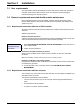
Section 2 General information 2.1 Safety information Please read the entire manual carefully before installing the software. Further information regarding the sc1000 controller is provided in the sc1000 controller manual. 2.2 Overview of product The sc1000 controller is designed for Internet-based communication with other users. The Ethernet port (wired connection) or the GSM/GPRS modem (wireless connection) serves as the communication interface for the sc1000.
General information 8
Section 3 Installation 3.1 User requirements Only appropriately trained specialist personnel are authorized to install and operate the computer system and sc1000 controller. Users must possess sound knowledge of network technology and computer systems. 3.2 General requirements associated with remote maintenance Every specified requirement must be fulfilled, otherwise remote maintenance and/or browser-based access to the sc1000 controller will not be possible, and damage to the system may occur. 3.2.
Installation 3.2.3 Scope of delivery The following components are included in the scope of delivery: • VPN client software tailored to the sc1000 controller • Manual Note: Please contact the manufacturer or responsible representative immediately if either of the components listed above are missing or defective. 3.3 Overview of the various connection options There are several ways to establish a connection between the sc1000 controller and a computer.
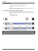
Installation Figure 2 Overview of alternative GPRS-based connections 1 GPRS connection without VPN tunnel (only possible if a CDA (Corporate Data Access) account is set up with the mobile network operator) 2 GPRS connection with secure VPN tunnel 3 GPRS connection via a VPN server of the mobile network operator 4 GPRS connection via fixed IP VPN server 5 GPRS connection via a fixed IP service and VPN server of the mobile network operator 11
Installation 3.4 Establish an Ethernet connection Figure 3 Ethernet connections 1 Basic Ethernet connection 2 Ethernet connection with secure VPN tunnel 3 Ethernet connection with fixed IP VPN server The Ethernet connection is the wired connection between a computer and the Ethernet port on the sc1000 controller. This Ethernet port is a 10 MB/s Ethernet connection located on the display module.
Installation 3.4.1 Establish a basic Ethernet connection Figure 4 Basic Ethernet connection If the sc1000 controller is located within the corporate network or is used for testing purposes, a basic Ethernet connection without VPN between the devices is advisable (Figure 4). 1. Connect the computer to the corporate network using an Ethernet cable. Make sure the Internet connection is fully functioning. Open various Internet pages to test the connection. 2.
Installation 6. Open a web browser on the computer. Enter the IP address of the sc1000 controller in the address bar (refer to point 3.). The login page for the sc1000 controller is displayed (Figure 6). 7. Enter the browser password (refer to Figure 6 and Section 3.4.1 on page 13). Note: A browser password is essential for web browser-based access to the sc1000 controller.
Installation 3.5 Install a VPN tunnel If the sc1000 controller is outside of the corporate network, a virtual private network (VPN) must be installed between the computer and the sc1000 controller. The VPN makes sure that the computer and sc1000 controller can communicate within a secure channel (tunnel) that is protected from unauthorized access. Windows 2000 and Windows XP both provide a built-in VPN server.
Installation From VPN server provider: • Configuration file (e.g. file with ".ovn" extension) • Certificate (e.g. file with ".crt" extension) • Key file (e.g. file with ".key" extension) 3. Start sc1000 controller. 4. Remove the cover of the SD card slot on the sc1000 controller display module (Figure 8). 1 3 2 Figure 8 Underside of display module 1 SD card slot 2 SD card slot cover 3 SD memory card 5. Insert the SD memory card into the SD card slot on the sc1000 controller. 6.
Installation 3.5.4 sc1000 controller: Install the VPN client using a web browser Note: The web browser installed on the computer must support file transfer via FTP. Microsoft Internet Explorer 7 only supports FTP protocol to a limited extent. 1. Make sure that the Ethernet connection between the sc1000 controller and computer is fully functioning. 2. Make sure that the web browser used supports FTP. 3.
Installation 6. Press the UPDATE button under NAVIGATION (Figure 10). Figure 10 UPDATE button 7. Click on the UPDATE DISPLAY MODULE link (Figure 11).
Installation 8. The "Upload files to sc1000" screen is displayed and the file manager interface (e.g. Microsoft Windows Explorer) is integrated into the browser window. Figure 12 Upload files to sc1000 controller 9. Click on ftp under FILES UPLOADED in the browser window. 10. Open the file manager (e.g. Microsoft Windows Explorer) and select the following files.
Installation 11. Copy the files and paste into the incoming directory in the web browser (Figure 13). Figure 13 Transfer files 12. Press the CONTINUE button. 13. Confirm the update on the sc1000 controller screen. The sc1000 controller now installs and configures the software automatically and must then be restarted. 3.5.5 sc1000 controller: Install the VPN client using Windows Explorer/FTP If the web browser does not support FTP protocol, data transfer via FTP in Windows Explorer is a viable alternative.
Installation 6. Copy the selected files to the following FTP directory: \tmp\incoming (Figure 14). Figure 14 FTP data transfer in Microsoft Windows Explorer 7. Open the web browser on the computer and enter the IP address of the sc1000 controller into the address bar. The login page for the sc1000 controller is shown. 8. Enter the browser password. 9. Press the UPDATE button. 10. Click on the UPDATE DISPLAY MODULE link. 11.
Installation 3.5.6 sc1000 controller: Check VPN installation 1. Open the web browser on the computer and enter the IP address of the sc1000 controller into the address bar. 2. Enter the browser password (refer to 3.4.1 on page 13). SYSTEM SETUP BROWSER ACCESS VPN VPN SYSTEM SETUP BROWSER ACCESS 3. On the SYSTEM SETUP>BROWSER ACCESS>VPN screen, make sure that the VPN tag is set to LAN. 4. On the SYSTEM SETUP>BROWSER ACCESS screen, make sure that the VPN tag is set to CONNECTION. 5.
Installation 3.5.7 Computer: Install the VPN client In order to communicate with the sc1000 controller via a VPN tunnel, a VPN client must also been installed on the computer. Important Note: If a VPN client is required on the sc1000 controller to establish a connection, OpenVPN must be installed as the VPN client on the computer. OpenVPN is a free VPN solution supported by several operating systems. The software can be downloaded from http://www.openvpn.net. 1.
Installation 3.5.8 Establish a VPN connection between the sc1000 controller and the computer 1. Start OpenVPN on the computer. 2. Enter username and password (Figure 16). These are supplied by the VPN server provider. Figure 16 Establish connection in OpenVPN 3. Enter the IP address (supplied by VPN server provider) of the sc1000 controller in the web browser on the computer (Figure 17). Note: The IP address can be found in the SYSTEM SETUP>BROWSER ACCESS> VPN>IP ADDRESS menu on the controller.
Installation 4. Enter the browser password (refer to Section 3.4.1 on page 13). The computer and sc1000 controller are now connected via a secure VPN tunnel. 3.
Installation All GPRS connections are managed via a mobile network operator.
Installation 3.6.3 GPRS connection without VPN tunnel Figure 19 GPRS connection without VPN tunnel A GPRS connection without a VPN tunnel is only possible if a CDA account has been set up with a mobile network operator. If this is the case, only the software settings need to be configured on the sc1000 controller (Section 3.6.2 on page 26); configuration of the VPN itself is part of CDA administration. Without a CDA account, it is only possible to connect to the Internet.
Installation 3.7 Establish a GPRS connection via fixed IP VPN server Figure 21 Establish a GPRS connection via fixed IP VPN server There are problems associated with connecting a sc1000 controller within a corporate network via a VPN tunnel. An external fixed IP service that assumes the roles of VPN server and interface to the mobile network operator is therefore a viable alternative.
Installation 3.8 GPRS connection via a VPN server of the mobile network operator Figure 22 GPRS connection via a VPN server of the mobile network operator The mobile network operator's CDA service (Corporate Data Access service) is used the transfer encrypted data between devices and the control center via GPRS. The corporate network is connected to the mobile communications network in one of two ways: via a rented line, which guarantees a fixed bandwidth and high degree of security, or via the Internet.
Installation 3.9 GPRS connection via fixed IP service and VPN server of the mobile network operator Figure 23 GPRS connection via fixed IP service and VPN server of the mobile network operator There are often problems associated with connecting to a company's own private network. For this reason, fixed IP providers usually also offer this service. The mobile network operator connects the user to the fixed IP provider via a private VPN tunnel.
Installation 3.10.2 sc1000 controller software settings The Modbus TCP software module is configured in the following sc1000 controller menus: SYSTEM SETUP MODBUS TCP MODBUS TCP Determines whether Modbus TCP is activated (ON) or not (OFF). TCP PORT Determines the TCP port. TELEGRAM Configures a slave based on individual data compilations from various devices. MODBUS ADDRESS Default value: 0 Determines the address (1 to 247) of the Modbus slave configured in the TELEGRAM menu.
Installation 3.10.3 Configure the Modbus TCP software module on the sc1000 controller SYSTEM SETUP 1. Set the MODBUS TCP tag to ON in the SYSTEM SETUP>MODBUS TCP menu. MODBUS TCP 2. Set the TCP PORT tag to 502 in the SYSTEM SETUP>MODBUS TCP menu. MODBUS TCP TCP PORT TELEGRAM MODBUS ADDRESS VIRTUAL SLAVES SIMULATION STATUS Note: It may be necessary to select an alternative port depending on the corporate firewall configuration.
Installation 3.10.4 Configure the Modbus telegram SYSTEM SETUP 1. Select SYSTEM SETUP>MODBUS TCP>TELEGRAM. MODBUS TCP 2. The configuration screen is displayed (Figure 25).
Installation 4. Select a probe/device and press the ENTER button. The probe/device (including serial number) is added to the telegram box (Figure 27). Figure 27 Device list 5. Select a tag (e.g. error or status) and press the ADD button. The tag selection box is displayed with all tags that are available for the probe/device (Figure 28). The error and status registers are identical for all probes/devices (Table 2 and Table 3). Figure 28 Tag selection window 6. Select tag and press the ENTER button.
Installation 7. Repeat steps to add additional probes/devices and tags. 8. Press the ENTER button to save the configuration. Table 1 Telegram list—Column description Column Description Data position in the configured Profibus slave (in 2 byte words) Modbus: Data position in the configured Modbus slave This slave contains holding registers beginning at 40001. Example: "0" means register 40001 and "11" means register 40012. 1 2 Tag name to identify the configured data.
Installation Table 3 Status register 36 Bit Status 1 Description 0 Calibration activated Calibration in progress, measurement value not up to date 1 Cleaning activated Cleaning in progress, measurement value not up to date 2 Service mode activated Device in "Service" mode, measurement value not up to date 3 General error message General error detected, refer to error text for details 4 Measurement value channel 0, poor quality Measurement accuracy is not within specified limits 5 Measur
Installation 3.10.5 System configuration example using Unity Pro Figure 30 through Figure 32 illustrate how a system can be configured using the Unity Pro PLC system software. Figure 30 Overview of system configuration using Unity Pro 1 Engineering station with sc1000 WebAccess 3 sc1000 controller with probe 2 E.g. Telemecanique TSX Premium P57 4634M 4 E.g.
Installation Figure 31 Connection of the sc1000 controller using Unity Pro (The language of the menu entries depends on the language settings) 1 IP address 2 Modbus address 38 3 Content of telegram
Installation Figure 32 System configuration using Unity Pro 1 Data order swapped 2 Telemecanique TSX Premium P57 4634M starts with offset 0 Telemecanique Modicon Quantum CPU 65160 with offset 1 39
Installation 40
Section 4 Error messages 4.1 GSM/GPRS See GSM error messages in the sc1000 controller manual. There are no specific status messages for GPRS. 4.2 VPN tunnel BROWSER ACCESS There are several status messages associated with establishing the VPN tunnel connection. These are displayed under SYSTEM SETUP>BROWSER ACCESS>VPN: VPN • OFF: The OpenVPN client is deactivated • LINK CONNECTION : The OpenVPN client is attempting to establish a connection to the server.
Error messages 4.4 Notification by e-mail in the event of error messages/warnings If an error occurs, an e-mail containing a description of the error can be sent to one or more recipients. Up to four configuration sets can be created for e-mail notification. Each configuration set includes the following (not exhaustive): • The e-mail address of the recipient. • Selected errors, warnings and events associated with connected probes that trigger e-mail notification.
Error messages 4.4.
Error messages 44
Section 5 Replacement parts and accessories Description SD card, 1 GB HACH LANGE display module with GSM modem Cat. no. LZY520 LXV402.99.
Replacement parts and accessories 46
Section 6 Glossary Table 7 Glossary Term Explanation APN Access Point Name; enables access to an external packet data network. DHCP Dynamic Host Configuration Protocol; enables a new computer to be connected to an existing network automatically. DNS Domain Name System Ethernet Physical layer for network communication, in accordance with IEEE standard 802.3. Fixed IP server Server that assigns fixed IP addresses to end devices, and manages these.
Glossary 48
Section 7 Contact HACH Company World Headquarters P.O. Box 389 Loveland, Colorado 80539-0389 U.S.A. Tel (800) 227-HACH (800) -227-4224 (U.S.A. only) Fax (970) 669-2932 orders@hach.com www.hach.com Repair Service in the United States: HACH Company Ames Service 100 Dayton Avenue Ames, Iowa 50010 Tel (800) 227-4224 (U.S.A. only) Fax (515) 232-3835 Repair Service in Canada: Hach Sales & Service Canada Ltd.
Contact 50