DOC026.52.00795 si792 C si792x C si792x C-FF si792x C-PA Contacting Conductivity 2-Wire Transmitters USER MANUAL December 2007, Edition 1 © HACH Company, 2007. All rights reserved. Printed in Germany.
Table of Contents Section 1 Specifications ......................................................... 5 Section 2 General information ........................................... 11 2.1 Safety information .................................................................... 11 2.1.1 Use of hazard information ................................................. 11 2.1.2 Precautionary labels.......................................................... 11 2.2 General product information.................................
Table of Contents 4.3 Display...................................................................................... 31 Section 5 Operation—4–20 mA/HART ............................ 33 5.1 Measure mode ......................................................................... 33 5.2 Configuration ............................................................................ 33 5.2.1 Output configuration .......................................................... 34 5.2.1.1 Concentration measurement ............
Table of Contents Section 8 Calibration .............................................................. 67 8.1 Calibration ................................................................................ 67 8.1.1 Enter cell constant............................................................. 68 8.1.2 Calibration with a calibration solution ................................ 68 8.1.3 Calibration by comparison or grab sample........................ 69 8.2 Temperature sensor adjustment ..........................
Table of Contents 4
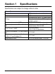
Section 1 Specifications Specifications are subject to change without notice. Transmitter Composition Display PBT (polybutylene terephthalate) LCD 3 knockouts for M20 x 1.5 strain reliefs Fittings 2 knockouts for ½ inch NPT or rigid metallic conduit Power requirements—HART 14–30 VDC (30 VDC maximum) Power requirements—FF and Profibus FISCO bus supply: 9 to 17.5 VDC PA Linear barrier: 9 to 24 VDC 4–20 mA floating; Loop current—HART 3.80–22.00 mA specifiable Current consumption—FF and Profibus < 13.
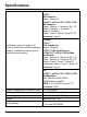
Specifications US: si792 C FM Listed for: Class I, Division 2 si792x C; si792x C-FF; si792x C-PA FM Listed for: Class I, Division 1, Groups A, B, C, D Class II, Division 1, Groups E, F Class III, Division 1 Class I, Zone 0, AEx ia, Group IIC T4 Enclosure: Type 2 Canada: si792 C CSA Certified to: Certification (may not apply to all sensors. Refer to the control drawing or Class I, Division 2 listing for certification information for si792x C CSA Certified and the sensor that is used).
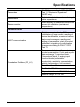
Specifications Passcodes Sensocheck Sensor monitor Modifiable according to FDA 21 CFR Part 11 “Electronic Signatures” (HART only) Polarization detection and monitoring of cable capacitance Direct display of measured values from sensor for validation (resistance/ temperature) Communication HART communication Foundation Fieldbus (FF_H1) Digital communication by FSK modulation of loop current, reading of device identification, measured values, status and messages, reading and writing of parameters, start
Specifications Profibus-PA (DPV1) Bus-powered device with constant current consumption. Cyclic and acyclic data exchange. Physical block, 2 analog input function blocks, 2 discrete input blocks, logbook block, alarm block. PNO directive: PROFIBUS-PA, Profile for Process Control Devices, Version 3.
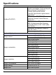
Specifications Measurement error3,4 < 1% measured value + 0.4 µS* c Temperature input Temperature sensor Pt100/PT1000/NTC 100 kΩ/ NTC 30 kΩ/NTC 8.55 kΩ (Betatherm) 2-wire connection Range, Pt100/Pt10001 –20.0 to 200.0 °C (–4 to 392 °F) Range, Pt100/Pt10002 –20.0 to 150.0 °C (–4 to 302 °F) Range, NTC 100 kΩ2 Range, NTC 30 kΩ –20.0 to 150.0 °C (–4 to 302°F) Range, NTC 8.55 kΩ1 Adjustment range Resolution –10.0 to 130.0 °C (14 to 266°F) Measurement error3,4 Temperature compensation –20.0 to 130.
Specifications 10
Section 2 General information 2.1 Safety information Please read this entire manual before unpacking, setting up, or operating this equipment. Pay attention to all danger and caution statements. Failure to do so could result in serious injury to the operator or damage to the equipment. To ensure that the protection provided by this equipment is not impaired, do not use or install this equipment in any manner other than that specified in this manual. 2.1.
General information Electrical equipment marked with this symbol may not be disposed of in European public disposal systems after 12 August of 2005. In conformity with European local and national regulations (EU Directive 2002/96/EC), European electrical equipment users must now return old or end-of life equipment to the Producer for disposal at no charge to the user.
General information 2.2 General product information 2.2.1 Product overview The si792 C and si792x C transmitters are used for measurement of electrical conductivity and temperature in liquids. Fields of application are: biotechnology, chemical industry, environment, food processing and water/waste-water treatment. The molded transmitter enclosure can be attached to a panel, wall, post or pipe railing.
General information and section 2.2.2.2 make the transmitter compliant with the requirements of FDA 21 CFR Part 11. 2.2.2.1 Electronic signatures for si792(x) C transmitters Device functions are protected by passcode access, which prevents unauthorized modification of device settings or manipulation of measurement results. Passcodes may be used as electronic signatures. Passcodes can be edited with the passcode editor (Appendix C on page 97). 2.2.2.
Section 3 Installation DANGER Explosion hazard. Trained personnel only must install or commission the equipment. DANGER Explosion hazard. Never connect items to the transmitter that are not specified on the control drawing. Do not connect or disconnect any equipment unless power has been switched off or the area is known to be non-hazardous. DANGER Explosion hazard.
Installation 3.1 Hazardous location installation Before installation, review the applicable Hazardous Location Control Drawing or ATEX EC-Type Examination certificate that is included with the instrument and the provided documentation CD. Follow all regulations specified for the installation location. Refer to the documentation CD for manuals provided in other languages.
Installation 3.2 Unpacking the transmitter Check the shipment for transport damage and make sure all components have been shipped complete.
Installation 3.3 Mechanical installation 3.3.1 Transmitter assembly Refer to Figure 1 and the following instructions to assemble the transmitter. 1. Insert the strain relief fittings in the holes of the back enclosure and secure with the hex nuts (Figure 2). 2. Insert the conduit hardware or plugs in the back enclosure and secure with the hex nuts. 3. Attach the display module to the back enclosure using the hinge pin. 3.3.
Installation Figure 2 Wall attachment dimensions 1 Breakout for wall mounting (2x) 2 Hole for pipe mounting (4x) 3 Strain relief (3x) 4 Breakout for panel mounting 5 Groove for panel mount gasket 6 Strain relief opening (3x) 7 Strain relief or ½ inch conduit opening (2x) Ø 21.5 mm [0.
Installation 3.4 Wiring Safety Information When making any wiring connections to the instrument, the following warnings and notes must be adhered to, as well as any warnings and notes found throughout the individual installation sections. For more safety information refer to section 2.1 on page 11. DANGER Always disconnect power to the instrument when making any electrical connections.
Installation 3.5 Electrical installation DANGER Explosion hazard. Do not connect any components that are not specified for the device. Always defer to the Hazardous Location Control Drawing. Prerequisites: • Review the applicable control drawing or ATEX EC-Type Examination certificate • Review the electrical code regulations • Review the regulations for electrical installations in hazardous locations, if appropriate (e.g.
Installation Figure 3 Wire preparation and insertion 1 Stripping lengths for cables 2 Stripping lengths for coaxial cables 3 Cable shield connector (not used) 4 ESD shield removed 5 Areas for screwdriver to pry terminal 22 6 Terminals (vary by model number) 7 Typical terminal 8 Seat insulation against connector 9 Removing terminal with screwdriver 10 Cable loop position in housing
Installation 3.5.2 Power and communication connections DANGER Explosion hazard. The AC power source for the power supply unit cannot exceed 250 VAC. Do not connect the transmitter directly to an AC power source. DANGER Explosion hazard. The output voltage of the power supply unit cannot exceed 30 VDC. The si792x transmitter must be connected to an appropriately certified explosion-proof power supply unit.
Installation 3.5.2.1 si792(x) C (4-20 mA/HART) wiring DANGER Explosion hazard. Never connect items to the transmitter that are not specified on the control drawing/ATEX EC-Type certificate. Refer to Figure 4 and Table 1 to connect the power supply to the si792(x) C transmitter. Figure 4 si792(x) C (4–20 mA/HART) wiring 1 HART connection (see warnings in section 3.6 on page 28) 2 Wiring terminals—see Table 1 Table 1 Terminal assignments—si792(x) C (4–20 mA/HART) Terminal No.
Installation 3.5.2.2 si792x C-FF and si792x C-PA wiring Refer to Figure 5 and Table 2 to connect power and communications to the si792x C-FF or si792x C-PA transmitters. Figure 5 si792x C-FF and si792x C-PA wiring 1 Wiring terminals—see Table 2 Table 2 Terminal assignments—si792x C-FF and si792 C-PA Terminal No.
Installation 3.5.3.1 2-electrode (3400 and 810x series) sensor wiring 1. Install jumpers between terminals 1-2, 3-4 and 4-5 (see Figure 6). 2. Use Table 3 to wire the sensor to the transmitter.
Installation 3.5.3.2 4-electrode sensor wiring 1. Install a jumper between terminals 4 and 5 as shown in Figure 7. 2. Use Table 4 to wire the sensor to the transmitter. Figure 7 si792 transmitter wiring for 4-electrode sensor 1 Jumper between terminal 4 and 5 2 Wiring terminals—see Table 4 Table 4 Terminal assignments—4-electrode sensor Terminal No.
Installation 3.6 HART communication connection DANGER Explosion hazard. Never connect items to the transmitter that are not specified on the control drawing. Do not connect or disconnect any equipment unless power has been switched off or the area is known to be non-hazardous. DANGER The si792x transmitter must be used with an explosion-proof HART communication device. Refer to the appropriate control drawing for the location of the HART (Rosemount) device.
Section 4 Interface and navigation The si792 transmitter user interface contains a display, indicators and keys for navigation and menu selection. 4.1 si792(x) C (4–20 mA/HART) interface Use the arrow and enter keys to scroll through the menu and change settings. Use the indicators to identify which mode the transmitter is in. Refer to Figure 8 to identify the keys and indicators of the si792(x) C transmitter.
Interface and navigation 4.2 si792x C-FF and si792x C-PA interface Refer to Figure 9 to identify the keys and indicators of the si792x C-FF or si792x C-PA transmitter.
Interface and navigation 4.3 Display Figure 10 identifies all of the possible icons and symbols that may be seen in the si792 transmitter display.
Interface and navigation 32
Section 5 Operation—4–20 mA/HART The following section describes how to operate the si792(x) C transmitter. 5.1 Measure mode The display shows the configured process variable (conductivity, concentration, resistivity or salinity) and the temperature value in the measuring mode. • To return to the measurement mode during calibration press CAL and ENTER. • To return to the measurement mode during configuration press CONF and ENTER.
Operation—4–20 mA/HART Note: During configuration the transmitter remains in the Hold mode for safety reasons. The loop current is frozen at the value specified in the o1.HoLD menu option. The Sensoface icon is inactive. The configuration mode indicator is shown (Figure 10 on page 31). 5.2.1 Output configuration Select the sensor CELL 2-electrode sensor (default) 4-electrode sensor Select the range and units o1. UnIT 0.000 µS/cm 00.00 µS/cm 000.0 µS/cm 0000 µS/cm 0.000 mS/cm 00.00 mS/cm 000.
Operation—4–20 mA/HART 5.2.1 Output configuration (continued) Select characteristic (Linear / Logarithmic curve) o1.CHAR1 LIN (default) LOG Linear/Logarithmic curve Specify the value for the 4 and 20 mA signals o1. 4mA o1.20mA o1. 4mA o1.20mA 000.0 mS 000.0 mS 1 mS (default) 100 mS (default) LIN: Enter current start LIN: Enter current end LOG: Enter current start LOG: Enter current end Set time averaging filter for reducing noise o1.
Operation—4–20 mA/HART acceptable range, “Err” will be shown and the value will not be accepted. To exit the menu and return to the measurement mode, press CONF and ENTER. Example: Set the output start point for the 4 mA signal to be 10.0 mS and the output end point to be 100 mS for the 20 mA signal. 1. Press CONF, enter passcode: 1200. The display will show Conf and then out.1MNU. 2. Press ENTER to access the output setup menu. The display will show CELL. 3.
Operation—4–20 mA/HART For accurate results use conductivity standards with the same conductivity range as the sample to calibrate the system. Table 6 Range of concentration Code Action -01- NaCl (default) -02- HCI o1.CoNC -03- NaOH -04- H2SO4 -05- HNO3 Range 0.00–9.99% by weight 0–100 °C (32–212 °F) 0.00–9.99% by weight 0–50 °C (32–122 °F) 0.00–9.99% by weight 0–100 °C (32–212 °F) 0.00–9.99% by weight 0–110 °C (32–230 °F) 0.00–9.99% by weight 0–50 °C (32–122 °F) 5.2.1.
Operation—4–20 mA/HART 5.2.1.4 Output signal during HOLD The output signal during hold periods can be maintained at the last measured value (Figure 11) or fixed at a specified value (Figure 12). The allowable range for the fixed value is 3.4 to 22 mA.
Operation—4–20 mA/HART 5.2.2 Temperature compensation configuration Select temperature unit tc.UnIT °C (default) °F Select temperature sensor tc.rTd PT100 (default for EU version) PT1000 (default for standard version) 30 NTC 8.55 NTC Select temperature compensation1 LIN (default) nLF tc. LIN nACL HCL nH3 OFF 1If Linear temperature compensation with entry of temperature coefficient (00.00–19.99%/ K). Reference temperature = 25 °C. Enter temperature coefficient 02.00%/K (default) (xx.
Operation—4–20 mA/HART accepted. To exit the menu and return to the measurement mode, press CONF and ENTER. 5.2.3 Alarm settings Select Sensocheck AL.SnSO CHECK ON CHECK OFF (default) Continuous Sensocheck evaluation of sensor function Enter alarm delay AL.dLY 0010 sec (default) Range: 0–600 sec LED in Hold mode AL.
Section 6 Fieldbus Operation—Foundation The following section describes how to navigate and operate the si792x C-FF transmitter. The transmitter can be operated as follows: • Direct interface with the transmitter (section 6.1) • Foundation Fieldbus communication (section 6.2 on page 44) 6.1 Configuration Use the configuration mode to specify the sensor, range and other parameters of the system. 6.1.1 Configuration steps Complete the following steps to configure the si792 transmitter. 1.
Operation—Foundation Fieldbus 6.1.2 Configuration menu Select the sensor In.CELL 2-electrode sensor (default) 4-electrode sensor Select the range and units In.UnIT 0.000 µS/cm 00.00 µS/cm 000.0 µS/cm 0000 µS/cm Conductivity 0.000 mS/cm 00.00 mS/cm 000.0 mS/cm (default) 0.000 S/m 00.00 S/m 00.00 MΩ·cm Resistivity 000.0 SAL Salinity (SAL) 00.00% -01- NaCl (default) -02- HCI Concentration -03- NaOH In.
Operation—Foundation Fieldbus 6.1.2 Configuration menu (continued) Select temperature compensation1 OFF LIN (default) tc. nLF nACL HCL nH3 Temperature compensation turned off Linear temperature compensation Enter temperature coefficient: Range: 0–19.99%/K (default: 2.00%/K) Reference temperature = 25 °C Natural waters (to EN 27888) Ultrapure water with NaCl traces (0–120 °C) Ultrapure water with HCl traces (0–120 °C) Ultrapure water with NH3 traces (0–120 °C) Select Sensocheck AL.
Operation—Foundation Fieldbus 6.2 Foundation Fieldbus communication Use the Foundation Fieldbus specification to set up and configure the si792 transmitter. The communication parameters are listed in the following sections. The sensor can be calibrated as described in section 6.2.4 on page 60. 6.2.1 Standard resource block (RB) The standard resource block describes the transmitter characteristics (manufacturer, device name, operating status, global status).
Operation—Foundation Fieldbus Table 7 Bus parameters—resource block (RB) (continued) Parameter Description HARD_TYPES RESTART FEATURES FEATURES Grant Deny Hardware type Restart Feature supported Feature selected CYCLE_TYPE Cycle type CYCLES_SEL Cycle selected MIN_CYCLE_T Min cycle time MEMORY_SIZE NV_CYCLE_T FREE_SPACE FREE_TIME SHED_RCAS SHED_ROUT FAULT_STATE SET_FSTATE CLR_FSTATE MAX_NOTIFY LIM_NOTIFY Memory size Non-volatile cycle time Free space Free time CONFIRM_TIME GRANT_DENY WRITE_LOCK
Operation—Foundation Fieldbus Table 7 Bus parameters—resource block (RB) (continued) Parameter BLOCK_ALM ALARM_SUM ACK_OPTION WRITE_PRI WRITE_ALM ITK_VER DEVICE_LOCK 46 Description Unacknowledged Alarm state Time stamp Sub-code Value Current Unacknowledged Unreported Disabled Automatic acknowledge option Write priority Unacknowledged Alarm state Time stamp Sub-code Value ITK_version Locks the device for local access.
Operation—Foundation Fieldbus 6.2.2 Standard analog input block (AI) Three Analog Input Function Blocks provide for cyclic transmission of measured values (currently measured value with status, alarm limits, freely selectable process parameter). 6.2.2.1 Operating modes Use the MODE_BLK parameter to set the following operating modes: • OOS—out of service. If not write-protected, access to all parameters is allowed. • MAN—manual • Auto—online, normal state 6.2.2.
Operation—Foundation Fieldbus 6.2.2.3 Data processing Use the L_TYPE parameter to apply a linearization function to the data. • Direct—data is sent directly from the TB to the AI without processing. The units for the XD_SCALE and OUT_SCALE parameters must be identical. • Indirect—data from the TB is linearly scaled from the input scale (XD_SCALE) to the output scale (OUT_SCALE). • Indirect square root—data is rescaled from the input scale (XD_SCALE) and recalculated using a root function.
Operation—Foundation Fieldbus 6.2.2.5 Bus parameters for the analog input block The bus parameters for the analog input function block (AI) are shown in Table 9.
Operation—Foundation Fieldbus Table 9 Bus parameters/analog input blocks (AI) (continued) Parameter GRANT_DENY IO_OPTS STATUS_OPTS CHANNEL L_TYPE LOW_CUT PV_TIME FIELD_VAL UPDATE_EVT BLOCK_ALM ALARM_SUM ACK_OPTION AlARM_HYS HI_HI_PRI HI_HI_LIM HI_PRI HI_LIM LO_PRI 50 Description Grant Deny IO Block Options Status Options Channel Linearization Type Low Cut Off Filter Time Percent Value Status Unacknowledged Update State Time Stamp Static Revision Relative Index Unacknowledged Alarm State Time Stamp Sub
Operation—Foundation Fieldbus Table 9 Bus parameters/analog input blocks (AI) (continued) Parameter Description LO_LIM LO_LO_PRI LO_LO_LIM Low Limit Low Low Priority Low Low Limit Unacknowledged Alarm State Time Stamp Sub-code Value Unacknowledged Alarm State Time Stamp Sub-code Value Unacknowledged Alarm State Time Stamp Sub-code Value Unacknowledged Alarm State Time Stamp Sub-code Value HI_HI_ALM HI_ALM LO_ALM LO_LO_ALM Default R/W –INF 0 –INF 0 0 0 0 0 0 0 0 0 0 0 0 0 0 0 0 0 0 0 0 R/W R/W R/W
Operation—Foundation Fieldbus 6.2.2.6 Cyclic measured value status The cyclic measured value status is shown in Table 10.
Transducer block ALERT_KEY STRATEGY TAG-DESC ST_REV Parameter The revision of the static data associated with the function block. Used by the host to determine when to re-read the static data. The user description of the intended application of the block. The strategy field can be used to identify a grouping of blocks. Can be used for any purpose by the user. Identification number that may be used by the host system to sort alarms and other device information.
54 R Unacknowledged Alarm State Time Stamp Subcode Value BLOCK_ALM R R/W R R/W R/W 1 1 8 2 2 1 1 8 2 1 2 1 1 1 1 R/W Bytes UPDATE_EVENT Allows the user to set the Target, Permitted, and Normal device mode. Displays the Actual mode. Target Actual Permitted Normal Reflects the error status associated with the hardware or software of the block. It is a bit string so multiple errors may be shown.
SENSOR_CONNECTION Output COLLECTION_ DIRECTORY XD_ERROR Identifies the transducer type. TRANSDUCER_TYPE Selects the connection of the sensor 36 1 2 4 R/W 1 A transducer block sub-code. XD_ERROR contains the highest priority alarm that has been R activated in the TB_DETAILED_STATUS parameter. A directory that specifies the number, starting indices, and DD item of IDs of the data collection in each transducer R within a transducer block. Used by the host for efficient transfer of information.
56 R/W 1 Selects the displayed primary value PRIMARY_VALUE_TYPE 4 1 R Shows the primary value and status Value Status PRIMARY_VALUE R/W Bytes Description Parameter uns8 DS_65 Data type 0 = 0.000 µS/cm 1 = 00.00 µS/cm 2 = 000.0 µS/cm 3 = 0000 µS/cm 4 = 0.000 mS/cm 5 = 00.00 mS/cm 6 = 000.0 mS/cm 7 = 0.000 S/m 8 = 00.00 S/m 9 = 00.00 MΩ cm 10 = SAL 11 = 00.
TEMP_SENSOR_TYPE SECONDARY_VALUE_ UNIT_2 SECONDARY_VALUE_2 Type of temperature sensor. The value entered must correspond to the temp. sensor being used. R/W 2 Process temperature value and status R 4 Value R 1 Status Degree C or degree F. Changes the unit of temperature being R/W 2 displayed and transmitted. R/W 2 Selects the solution used for concentration measurement.
58 R/W 1 Selects the temperature compensation TEMP_COMPENSATION float uns8 Starts the 1st part of conductivR/W 1 ity product calibration. CAL_SAMPLE_PRD 0 to 20.00 Default: 1.0 0 = Nop 1 = Sample -10 to +10K Default: 0 float R/W 4 Default: 0 Ω float Sets the cell constant. 00.00 to 19.99%/ K Default: 2.
R/W Bytes 1 Shows the last error. Shows the current status of the R Sensoface. LAST_ERROR SENSOFACE_STATUS Identification and local parameter setting SW_REV_LEVEL Software revision number HW_REV_LEVEL Hardware revision number 2 R Sets the LED to HOLD mode. ALARM_LED_MODE R R 2 1 R/W 1 uns16 uns8 uns8 uns16 uns8 uns8 Enables or disables Sensocheck. SENSOCHECK R/W 1 uns8 float float Data type Sets the device to HOLD mode.
Operation—Foundation Fieldbus 6.2.4 Calibration via Foundation Fieldbus The transmitter can be calibrated via Foundation Fieldbus using the comparison or grab sample method. 1. Make sure the system is configured for conductivity or resistivity (PRIMARY_VALUE_TYPE = µS/cm, mS/cm, S/m or MΩ/cm). 2. Collect a grab sample and set CAL_SAMPLE_PRD to sample. The conductivity value of the sample is stored. After writing, the parameter is automatically reset to NOP (no operation). 3.
Section 7 Operation—Profibus PA The following section describes how to navigate and operate the si792x C-PA Profibus-PA transmitter. The transmitter can be operated as follows: • direct interface with the transmitter (section 7.1) • remote operation from the control station (section 7.2 on page 63) Note: Calibration must be completed by direct interface with the transmitter. 7.1 Configuration Use the configuration mode to specify the sensor, range and other parameters for the system. 7.1.
Operation—Profibus PA 7.1.2 Configuration menu Select the sensor CELL 2-electrode sensor (default) 4-electrode sensor Select the range and units 0.000 µS/cm 00.00 µS/cm 000.0 µS/cm 0000 µS/cm Conductivity 0.000 mS/cm 00.00 mS/cm 000.0 mS/cm (default) 0.000 MΩ/cm 00.00 MΩ/cm Resistivity 000.0 MΩ/cm 000.
Operation—Profibus PA 7.1.2 Configuration menu (continued) Select temperature compensation1 OFF LIN (default) tc nLF –01– FCT –02– FCT –03– FCT Temperature compensation turned off Linear temperature compensation Enter temperature coefficient: Range: 0–19.99%/K (default: 2.00%/K) Reference temperature = 25 °C Enter temperature coefficient 02.00%/K (default) (xx.
64 6 7 8 9 10 Sensocheck Cell constant Calibration Configuration 0101 01xx 4 Temp range violation Temperature probe 0000 11xx 3 5 0000 11xx 2 0100 0111 0100 1111 1010 00xx 1010 01xx 0100 0111 0100 1111 0100 0111 0100 1111 0100 0111 0100 1111 0000 11xx 1 Conductance range violation Factory settings defective Configuration data defective, Gaincheck Memory error (RAM, ROM, EPROM) Cond, sal range violation Cause Function check CONF RUNNING CAL RUNNING CHK SLOPE Function check CHK SENSOR
HOLD (Device state = Maintenance) HI_HI_LIM FB analysis Cond/MO/SAL HI_LIM FB analysis Cond/MO/SAL LO_LIM FB analysis Cond/MO/SAL LO_LO_LIM FB analysis Cond/MO/SAL HI_HI_LIM FB temperature HI_LIM FB temperature LO_LIM FB temperature Cause 0100 0111 0100 1111 1000 1110 1000 1010 1000 1001 1000 1101 1000 1110 1000 1010 1000 1001 11 12 13 14 15 16 17 18 No.
66 LO_LO_LIM FB temperature Logbook empty Cause 1000 1101 Function check 19 20 No.
Section 8 Calibration 8.1 Calibration Important Note: Stabilize the temperature during calibration. Note: Only qualified personnel should conduct the tasks described in this section of the manual. The transmitter is adjusted to the sensor through the calibration. Use the following methods and passcodes for calibration as described in Table 14.
Calibration 8.1.1 Enter cell constant 1. Press CAL and enter passcode: 1100, ENTER. CAL CELL will be displayed for 3 seconds. 2. Use the UP ARROW and RIGHT ARROW to enter the value of the cell constant of the connected sensor. The conductivity value will be displayed also. Note: For Hach or GLI contacting conductivity sensors, the cell constant is usually printed on a tag with the sensor wiring. Note: A cell constant change will change the conductivity value.
Calibration to determine the temperature-corrected conductivity value of the calibration solution. Note: If the entry of the calibration solution value takes longer than 6 seconds, the display will alternate between showing the cell constant and the temperature value. 4. Press ENTER to save the value. 5. The display will show the new cell constant value and CELL. Press ENTER. 6. The transmitter remains in HoLD mode. Press ENTER again.
Calibration 3. Measure the grab sample with a laboratory or portable meter. 4. Press CAL, enter passcode: 1105, ENTER to access the product calibration once more. The display will briefly show CAL PRD and then CALC. 5. Edit the displayed value to match the value measured by the laboratory or portable meter and press ENTER. The newly calculated cell constant will be displayed. 6. Press ENTER to end the calibration. The display will show the measured value alternating with Hold.
Section 9 Maintenance DANGER Explosion hazard. Only qualified personnel should conduct the tasks described in this section of the manual. DANGER Electrostatic hazard. Follow the instructions in Electrostatic Discharge (ESD) Considerations on page 20 before conducting any maintenance tasks. 9.1 Cleaning the instrument Use only a moistened antistatic, lint-free cloth to remove dust, dirt and spots from the external surfaces of the transmitter. Use a mild household cleaner if necessary. 9.
Maintenance 72
Section 10 Troubleshooting 10.1 Sensoface The Sensoface feature is active whenever Sensocheck is active. This feature monitors the sensor for defects in the sensor or cable, and indicates the maintenance status of the sensor (see Table 15). Table 15 Sensoface description Sensoface Description The sensor is operating properly. The operation of the sensor is acceptable, but will require replacement soon. The sensor is no longer usable. Replace the sensor. 10.
Troubleshooting Table 16 Error descriptions Display Problem Description Make sure that the correct sensor is installed and that it is operating correctly. Check sensor connection or replace cables. Sensor is defective Make sure that there are no Polarization effects at the sensor. Refer also to Err 33, Table 17. Make sure that the measured temperature is within Temperature the range of the temperature compensation table error (temperature compensation, concentration, salinity). 10.
Troubleshooting Table 17 Error codes (continued) Code ERR 03 ERR 11 ERR 12 ERR 13 Description Corrective action Test the temperature sensor wiring. Make sure that the correct temperature sensor was selected in the configuration menu. For Hach GLI 3400 Temperature sensor icon series sensors use Pt1000. flashes; open or short circuit; Measure the resistance of temperature range exceeded the temperature sensor in the sensor to make sure of a correct reading.
Troubleshooting Table 17 Error codes (continued) Code Description Sensocheck icon flashes; Sensoface icon active (see section 10.2) ERR 33 Temperature icon flashes; Sensoface icon active (see section 10.2) ERR 98 ERR 99 CONF flashes; configuration or calibration data is defective. Memory error in the program. FAIL flashes; EEPROM or RAM defective Corrective action Make sure that the correct sensor is installed and that it is operating correctly. Check sensor connection or replace cables.
Troubleshooting 10.4 Diagnostic tests (continued) Function Description From the measuring mode press CONF and enter passcode ‘2222’ for the validation of the sensor and a complete View sensor measured-value processing. The measured resistance is monitor shown in the main display and the measuring temperature is shown in the lower display. Press ENTER to return immediately to the measuring mode. From the measuring mode, press CONF and enter passcode View the last error ‘0000’.
Troubleshooting 78
Section 11 Replacement parts 11.1 si792 transmitter versions Description Catalog number Standard versions—default set for Hach 3400 sensors (not available in EU) si792 C, contacting conductivity, CID2 si792x C, contacting conductivity, CID1; ATEX Zone 1 si792x C-PA, contacting conductivity, CID1; ATEX Zone 1 si792x C-FF, contacting conductivity, CID1; ATEX Zone 1 LXV501.99.70012 LXV501.99.70112 LXV501.99.76112 LXV501.99.
Replacement parts 80
Section 12 Contact information HACH Company World Headquarters P.O. Box 389 Loveland, Colorado 80539-0389 U.S.A. Tel (800) 227-HACH (800) 227-4224 (U.S.A. only) Fax (970) 669-2932 orders@hach.com www.hach.com Repair Service in the United States: HACH Company Ames Service 100 Dayton Avenue Ames, Iowa 50010 Tel (800) 227-4224 (U.S.A.
Contact information HACH LANGE FRANCE S.A.S. 33, Rue du Ballon F-93165 Noisy Le Grand Tél. +33 (0)1 48 15 68 70 Fax +33 (0)1 48 15 80 00 info@hach-lange.fr www.hach-lange.fr HACH LANGE SA Motstraat 54 B-2800 Mechelen Tél. +32 (0)15 42 35 00 Fax +32 (0)15 41 61 20 info@hach-lange.be www.hach-lange.be DR. LANGE NEDERLAND B.V. Laan van Westroijen 2a NL-4003 AZ Tiel Tel. +31(0)344 63 11 30 Fax +31(0)344 63 11 50 info@hach-lange.nl www.hach-lange.nl HACH LANGE APS Åkandevej 21 DK-2700 Brønshøj Tel.
Contact information HACH LANGE 8, Kr. Sarafov str. BG-1164 Sofia Tel. +359 (0)2 963 44 54 Fax +359 (0)2 866 04 47 info@hach-lange.bg www.hach-lange.bg HACH LANGE SU ANALİZ SİSTEMLERİ LTD.ŞTİ. Hilal Mah. 75. Sokak Arman Plaza No: 9/A TR-06550 Çankaya/ ANKARA Tel. +90 (0)312 440 98 98 Fax +90 (0)312 442 11 01 bilgi@hach-lange.com.tr www.hach-lange.com.tr ΗΑCH LANGE E.Π.Ε. Αυλίδος 27 GR-115 27 Αθήνα Τηλ. +30 210 7777038 Fax +30 210 7777976 info@hach-lange.gr www.hach-lange.gr HACH LANGE E.P.E.
Section 13 Warranty, liability and complaints The manufacturer warrants that the product supplied is free of material and manufacturing defects and undertakes the obligation to repair or replace any defective parts at zero cost. The warranty period for instruments is 24 months. If a service contract is taken out within 6 months of purchase, the warranty period is extended to 60 months.
Warranty, liability and complaints To avoid or limit consequential damage, it is therefore recommended to design the control loop such that a malfunction in an instrument results in an automatic change over to the backup control system; this is the safest operating state for the environment and the process.
Warranty, liability and complaints 86
Appendix A Calibration solutions Table 18 Potassium chloride solutions (conductivity in mS/cm) Concentration1 Temperature °C °F 0.01 mol/L 0.1 mol/L 1 mol/L 0 5 10 15 16 17 18 19 20 21 22 23 24 25 26 27 28 29 30 31 32 33 34 35 36 32 41 50 59 60.8 62.6 64.4 66.2 68 69.8 71.6 73.4 75.2 77 78.8 80.6 82.4 84.2 86 87.8 89.6 91.4 93.2 95 96.8 0.776 0.896 1.02 1.147 1.173 1.199 1.225 1.251 1.278 1.305 1.332 1.359 1.386 1.413 1.441 1.468 1.496 1.524 1.552 1.581 1.609 1.638 1.667 1.696 7.15 8.22 9.33 10.
Calibration solutions Table 19 Sodium chloride solutions (mS/cm) Temperature 88 Concentration °C °F 0 1 2 3 4 5 6 7 8 9 10 11 12 13 14 15 16 17 18 19 20 21 22 23 24 25 26 27 28 32 33.8 35.6 37.4 39.2 41 42.8 44.6 46.4 48.2 50 51.8 53.6 55.4 57.2 59 60.8 62.6 64.4 66.2 68 69.8 71.6 73.4 75.2 77 78.8 80.6 82.4 0.01 mol/L1 0.631 0.651 0.671 0.692 0.712 0.733 0.754 0.775 0.796 0.818 0.839 0.861 0.883 0.905 0.927 0.95 0.972 0.995 1.018 1.041 1.064 1.087 1.111 1.135 1.159 1.183 1.207 1.232 1.256 0.
Calibration solutions Table 19 Sodium chloride solutions (mS/cm) (continued) Temperature Concentration °C °F 29 30 31 32 33 34 35 36 84.2 86 87.8 89.6 91.4 93.2 95 96.8 0.01 mol/L1 1.281 1.306 1.331 1.357 1.382 1.408 1.434 1.46 0.1 mol/L1 Saturated2 11.552 11.773 11.995 12.22 12.445 12.673 12.902 13.132 272.1 277.4 282.7 288 293.3 298.7 304.1 309.5 1Data source: Test solutions calculated according to DIN IEC 746-3 source: K. H. Hellwege (Editor), H. Landolt, R.
Calibration solutions 90
Appendix B Concentration curves B.1 Sodium chloride solution -01- NaCl Refer to Figure 13 for the conductivity of sodium chloride solution at various concentrations and temperatures.
Concentration curves B.2 Hydrochloric acid -02- HCl Refer to Figure 14 for the conductivity of hydrochloric acid (HCl) at various concentrations and temperatures.* Figure 14 The concentration of hydrochloric acid -02- HCl (weight %) * Source: Haase/Sauermann/Dücker; Z. phys. Chem. New Edition, Vol.
Concentration curves B.3 Sodium hydroxide solution -03- NaOH Refer to Figure 15 for the conductivity of sodium hydroxide solution (NaOH) at various concentrations and temperatures.
Concentration curves B.4 Sulfuric acid -04- H2SO4. Refer to Figure 16 for the conductivity of sulfuric acid at various concentrations and temperatures.* Figure 16 The concentration of sulfuric acid -04- H2SO4 (weight %) * Source: Darling; Journal of Chemical and Engineering Data; Vol.9 No.
Concentration curves B.5 Nitric acid -05- HNO3. Refer to Figure 17 for the conductivity of nitric acid at various concentrations and temperatures.* Figure 17 The concentration of nitric acid -05- HNO3 (weight %) * Source: Haase/Sauermann/Dücker; Z. phys. Chem. New Edition, Vol.
Concentration curves 96
Appendix C Passcode editor For applications requiring compliance to FDA 21 CFR Part 11, certain device functions must be protected with passcodes. Passcodes can be changed in the passcode editor. If passcode protection is not required, use the preset passcodes (Table 20). To activate the passcode editor: 1. Press CONF. 2. Enter 1989, the administrator passcode. The initial screen will show for approximately 3 seconds, then proceed to the next function. 3. Use the ARROW keys to change the passcode. 4.
Passcode editor 1 Not available with si792x C-PA Important Note: The passcode editor cannot be accessed without the administrator passcode. Record changes in a secure location. It is not possible to override this system if the passwords are lost. The unit must be exchanged. Contact technical support for assistance.
Index 22 mA signal........................................................................................ 37 4–20 mA output error notification .......................................................................... 37 A assembly transmitter ................................................................................... 18 audit trail.............................................................................................. 14 C calibration .......................................................
Index display ................................................................................................. 31 E electrostatic discharge (ESD) .............................................................. 20 error codes .......................................................................................... 74 F FDA compliance .................................................................................. 13 H hold mode during configuration.......................................................
Index general ........................................................................................ 11 wiring ........................................................................................... 20 Sensocheck description ................................................................................... 73 setting on or off ........................................................................... 40 Sensoface .......................................................................................
Index 102