Catalog Number DOC026.52.
Catalog Number DOC026.52.00769 Surface Scatter® 7 sc Turbidimeter USER MANUAL Edition 2 November 2006 © Hach Company, 2006. All rights reserved. Printed in Germany.
Visit us at www.hach.
Table of Contents Section 1 Specifications .........................................................................................................5 Section 2 General information ...............................................................................................9 2.1 Safety information ....................................................................................................................... 9 2.1.1 Use of hazard information ..........................................................
Table of Contents Section 7 Troubleshooting ...................................................................................................47 7.1 7.2 7.3 7.4 Error Codes ...............................................................................................................................47 Warnings ...................................................................................................................................47 Event codes ....................................................
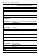
Section 1 Specifications Specifications are subject to change without notice Range 0.01–9999.9 nephelometric turbidity units (NTU) Accuracy ± 5% of reading or ± 0.1 NTU (whichever is greater) from 0.01 to 2000 NTU; ± 10% of reading from 2000 to 9999 NTU Resolution (displayed) 0.01 NTU up to 999.99 NTU; 0.1 NTU from 1000.0 to 9999.9 NTU Repeatability Better than ± 1.0% of reading or ± 0.04 NTU, whichever is greater for each range.
Specifications Figure 1 Maximum ambient temperature vs.
Specifications Temp 58 56 sc 1000 Ambient T (°C) 54 52 50 48 46 44 42 40 38 20 22 24 26 28 30 32 34 36 38 40 42 44 46 48 50 52 54 56 58 Probe Load (watts) Figure 2 Maximum ambient temperature vs.
Visit us at www.hach.
Section 2 General information 2.1 Safety information Please read this entire manual before unpacking, setting up or operating this equipment. Pay attention to all danger and caution statements. Failure to do so could result in serious injury to the operator or damage to the equipment. To ensure that the protection provided by this equipment is not impaired, do not use or install this equipment in any manner other than that specified in this manual. 2.1.
General information 2.2 General product information 2.2.1 Instrument description The Surface Scatter® 7 sc (SS7 sc) Turbidimeter is a sensitive, continuous-monitoring instrument designed for measuring turbidity in fluids. The instrument design is based on the nephelometric principle, where light scattered by particles suspended in the fluid is measured to determine the relative amount of particulate matter in the fluid. It meets all U.S.
General information 2.2.1.1 Controller The SS7 sc and SS7 sc-HST operate in conjunction with an sc100 controller. The controller enclosure houses the keypad, display, microprocessor board and power supply components. Operating controls and indicators are on the controller. The controller is used to program the instrument for turbidity level alarm set points and to perform diagnostic self-tests and programming operations.
General information Figure 4 SS7 sc components 1 Detector assembly (Cat. No. 71221-00) 5 Bulkhead fitting, 1-in. NPT (Cat. No. 40355-00) 2 Light source assembly (Cat. No. 45004-00) 6 Bulkhead fittings, ¾-in. NPT (Cat. No. 40311-00) 3 To sc100 7 Turbidimeter body (Cat. No. 45002-00) 4 Cord grip (Cat. No.
General information Figure 5 Optical diagram 1 Detector assembly 5 Light beam 9 Instrument drain 2 Scattered light 6 Over-flowing sample 10 Refracted light 3 Lens 7 Overflow drain 11 Turbidimeter body 4 Lamp 8 Sample in 12 Reflected light 2.2.2 Surface Scatter 7 sc High Sample Temperature The Surface Scatter 7 sc High Sample Temperature Turbidimeter (SS7 sc-HST) has been designed for high sample temperature.
General information Figure 6 SS7 sc-HST components 1 Flow multiplier 8 Cord grip (Cat. No. 61287-01) 2 ¾-in. hose 9 Bulkhead fitting, 1-in. NPT (Cat. No. 40355-00) 3 Threaded disk (Cat. No. 40299-00) with ¼-in. screw (Cat. No. 7858-11) 10 Drain trap 4 Detector assembly (Cat. No. 71221-00) 11 1-in. NPT gravity drain 5 Vent cover (Cat. No. 40294-00) 12 Bulkhead fittings, ¾-in. NPT (Cat. No. 40311-00) 6 Light source assembly (Cat. No. 45004-00) 13 Turbidimeter body (Cat. No.
Section 3 Installation DANGER Only qualified personnel should conduct the tasks described in this section of the manual. The SS7 sc/sc controller product configuration is not intended for installation in hazardous locations. The tasks described in this section requires individuals to be technically knowledgeable of the associated dangers. Burns, shock, eye damage, fire and chemical exposure may occur if this work is not done by qualified personnel.
Installation Figure 7 Installation kit items1 1 Formazin stock solution, 4000 NTU, 500 mL 6 Washer, ¼ ID x 1.00 OD (4x) 2 Brush, cylinder, size 2 7 Adapter, barb fitting, ¾” NPT to ¾” ID hose barb (2x) 3 Calibration cup, SS7 sc 8 Adapter, barb fitting, 1” NPT to 1” ID hose 4 Light source alignment plate 9 Nipple, ¾” NPT 5 Wall mounting kit 10 Drain valve 1 See 16 Section 8 Replacement parts and accessories on page 51.
Installation 3.3 Mechanical installation 3.3.1 Environmental requirements The SS7 sc and SS7 sc-HST enclosures are designed for general-duty, indoor installation. Ambient temperatures within specifications are allowed, but best performance will result if temperature does not change rapidly. Do not mount in direct sunlight. Shield from dripping water. The controller enclosure is designed to protect the electronics from typical conditions in water treatment and industrial facilities. 3.3.
Installation Figure 8 SS7 sc and SS7 sc-HST installation drawing 1 Door hinges (4x) 7 Ball valve 2 Flow multiplier (SS7 sc-HST only) 8 ¾-in. NPT nipple 3 Ventilator (2x) 9 1-in. NPTF bulkhead fitting 4 Cable assembly 10 ¾-in.
Installation Figure 9 Instrument leveling 1 Level 3.3.4 Installing the optional heat exchanger An optional heat exchanger (Cat. No. 48551-00) is available for the SS7 sc-HST (Figure 10 on page 20). The heat exchanger reduces sample temperatures that exceed the temperature requirements of the instrument. It can reduce sample temperatures of up to 100 °C but is not suitable for steam or super-heated water. A source of cooling water is required.
Installation Figure 10 Heat exchanger dimensions 3.3.5 Installing the 3-way ball valves CAUTION Installation should be performed by qualified technical personnel to ensure adherence to all applicable electrical and plumbing codes. Refer to the Auto Flush Kit Instruction Sheet (Cat. No. 46692-88) for complete installation instructions. 3.4 Installing a sample line Sample lines diameter must be appropriate for the sample type.
Installation Figure 11 Sampling techniques 1 Poor 5 Sediment (typical) 2 Sampling line to sample unit 6 Good 3 Sample flow 7 Best 4 Air (typical) 3.5 Connecting hydraulics Note: When connecting the hydraulics to the bottom of the unit, hold the ¾-in. bulkhead adapters on the inside of the enclosure with the door open. The sample in, body drain and overflow drain are connected to the instrument as shown in Figure 5 on page 13.
Installation Figure 12 SS7 sc-HST plumbing diagram 1 Optional items 14 Sample unit 2 Bubble trap 15 sc100 3 3-way ball valve (Auto Flush Kit) 16 Customer supplied power on/off switch box (NEMA 4X) required for agency compliance 4 Cooling water to drain 17 Power in for sc100 5 Cooling water out 18 ¾-in. NPT adapter (supplied) 6 Flow control valve 19 Drain Trap (Customer-supplied) 7 Sample in 20 1-in.
Installation Figure 13 SS7 sc plumbing diagram 1 Sample in 9 2 Flow control valve (recommended) 10 ¾-in. NPT nipple (supplied) Power in for sc100 3 ¾-in.NPT x ¾-in. ID Hose Adapter (supplied with bubble trap) 11 Ball valve (supplied) 4 Bubble trap (optional) 12 ¼-in. air purge fitting (50 SCFH instrument air max) 5 127 mm (5 in.) minimum 13 1-in.
Installation 3.6 Connecting the air purge fitting Air purge helps control condensation and corrosive vapors within the sample unit and is recommended. Use dry instrument air only. See Figure 12 and Figure 13 for installation details. 3.7 Electrical installation 3.7.1 Wiring safety information When making any wiring connections to the instrument, the following warnings and notes must be adhered to, as well as, any warnings and notes found throughout the individual installation sections.
Installation Figure 14 Attaching the SS7 sc/SS7 sc-HST using the quick-connect fitting 3.7.2.2 Hard-wiring the SS7 sc to the sc100 controller 1. Disconnect power to the controller if powered. 2. Open the controller cover. 3. Disconnect and remove the existing wires between the quick-connect and terminal strip J5 (Figure 15). 4. Remove the quick-connect fitting and wires and install the threaded plug on the opening to maintain the environmental rating. 5. Cut the connector from the SS7 sc cable. 6.
Installation Table 4 Wiring the SS7 sc at terminal block J5 Terminal number Terminal designation Wire color 1 Data (+) Blue 2 Data (–) White 3 Service request No connection 4 +12 V dc Brown 5 Circuit common Black 6 Shield Shield (gray wire in existing quick disconnect fitting) Figure 15 Hard-wiring the SS7 sc 1 26 From SS7 sc 2 Disconnect power
Section 4 System startup 4.1 General operation 1. Plug the SS7 sc/SS7 sc-HST into the unpowered controller by aligning the orientation tab on the cable connector with the channel in the controller connector. 2. Push in and turn the threaded collar to secure the connection. Tug gently to check the connection. 3. After all plumbing and electrical connections have been completed and checked, supply power to the system. 4.
Visit us at www.hach.
Section 5 Operation 5.1 Sensor setup When a sensor is initially installed, the sensor name will be displayed. To change the sensor name refer to the following instructions: 1. From the Main Menu, select SENSOR SETUP and confirm. 2. If multiple sensors are attached to the controller, choose SELECT SENSOR>SS7 SETUP and confirm. 3. Select CONFIGURE and confirm. 4. Select EDIT NAME and edit the name. Confirm or cancel to return to the Sensor Setup menu 5.1.
Operation 5.2 Sensor data logging The controller provides two data logs (one for each sensor) and two event logs (one for each sensor). The data logs store the measurement data at selected intervals. The event log stores a variety of events that occur on the devices such as configuration changes, alarms and warning conditions. The data logs are stored in a packed binary format and the event logs are stored in a CSV format.
Operation 5.4 Sensor setup menu (continued) DIAG/TEST INST STATUS Displays the software and hardware versions. SERIAL NUMBER Displays the serial number of the sensor. INT TEMP Displays the internal temperature of the sensor electronics in °C. DEFAULT SETUP Restores the sensor factory default settings. Calibration is not affected. POWER CHECK Displays the electrical statistics for the sensor. SERVICE MODE Allows SS7 sc to be run in normal or service mode.
Operation 8. If no selection is made for a set period of time, the screen will prompt to remix the standard to avoid a change in the value of the standard. a. Open the SS7 sc and remix the standard. b. Close the door and confirm to continue. 9. Confirm to calibrate. When the calibration is completed successfully, confirm to accept the calibration. 10. Enter the initials of the user performing the calibration and confirm.
Operation 7. Confirm to calibrate. When the calibration is completed successfully, the display will show GOOD CAL! and the new calibration gain value. Confirm to accept the calibration. 8. Follow the prompt and enter the initials of the user performing the calibration. Confirm. 9. The controller will prompt for NEW BASELINE. Confirm to establish a new baseline or press BACK to exit. 10. Remove the calibration cylinder from the body. The instrument is now calibrated. 11.
Operation calibrated. Take a grab sample from the on-line instrument drain or sample inlet line and immediately measure its turbidity in the laboratory instrument. If the on-line instrument reading is off by more than 5%, use the calibration procedure detailed in section 5.5.2 on page 31 to input the new standard value. If this calibration method is used, it is not necessary to use the calibration cylinder. 5.5.2.
Operation 6. Open the SS7 sc to remove the plate. Restart the sample flow and close the door. Confirm to return the instrument to measurement mode. Note: After confirmation of return to measurement mode, the instrument will equilibrate for 2 minutes before the output mode changes. Instrument measurements will show on the display, but the value will flash and a “OUT MODE WARN” warning will display until the 2-minute equilibration period is complete. 5.5.
Operation 9. When the displayed turbidity value is stable, confirm to select the measured reading. After confirming the reading: • GOOD VER! will be displayed if the verification is good, with an option to continue or to abort. Confirm to continue. Enter the operator initials and confirm. • BAD VER! will be displayed if the verification is bad, with an option to repeat or exit. To repeat the verification, confirm to return to the VALID SN screen (step 6). 10. Open the SS7 sc to remove the plate.
Operation 5. Confirm to view the previous calibrations. After scrolling through all 12 histories, the display will return to the calibration menu level. To view verification history: 1. From the Main Menu, select SENSOR SETUP and confirm. 2. If multiple sensors are attached to the controller, choose SELECT SENSOR>SS7 SETUP and confirm. 3. Select CALIBRATE and confirm. 4. Select VERIFICATION and confirm. 5. Select VER HISTORY and confirm. The most recent verification will be displayed on the screen. 6.
Operation 5.7 Operating the SS7 sc-HST • If condensation forms in the enclosure, increase the air pressure (and flow) by increasing the air pressure setting of the pressure regulator for the flow multiplier. • Make sure the bubble trap is working. Bubbles on the surface of the liquid will cause incorrect readings. • If deposits accumulate inside the unit, wash the inside with warm water spray.
Section 6 Maintenance DANGER Only qualified personnel should conduct the tasks described in this section of the manual. The nature of tasks described in this section of the manual requires individuals to be technically knowledgeable of the associated dangers. Burns, shock, eye damage, fire and chemical exposure may occur if this work is not done by qualified personnel. Always review appropriate Material Safety Data Sheets (MSDS) before working with chemicals. 6.
Maintenance 6.3.1 Cleaning Sediment may collect in the turbidimeter body and on the overflow weir. Algae may also form. The turbidimeter body should be drained and flushed—on a schedule determined by visual inspection—to remove accumulated sediment. Algae can be removed with a large bottle brush and a sterilizing solution such as dilute chlorine bleach. Samples containing large amounts of settleable solids may cause frequent accumulation of solids in the turbidimeter body.
Maintenance 5. Wipe the replacement lamp clean to remove any dust and fingerprints. Fingerprints left on the glass bulb can permanently damage the lamp. Install the lamp in the light source block. 6. Slide the notched spacer over the lamp cable with the notch away from the lamp base. Route the lamp cable through the notches. Install the lamp and spacer into the end of the housing with the spacer notch aligned with the notch in the housing. 7. Install the end plate using the two screws removed in step 3. 8.
Maintenance Figure 17 Lamp replacement 1 Lamp cable 6 Spacer 2 End plate 7 Housing 3 Notched spacer 8 Light source assembly 4 Back plate 9 Lamp 5 Base 42
Maintenance Figure 18 Alignment details 1 Flat notch 6 Light source assembly 2 Alignment template 7 Mounting screws 3 Calibration cylinder 8 Target area 4 Turbidimeter body 9 Adjust light source to align light beam in target area 5 Install calibration cylinder and alignment template 6.4.2 Light source assembly maintenance No maintenance of the light source assembly is normally necessary beyond changing the lamp.
Maintenance Figure 19 Light source assembly 1 Shield assembly (Cat. No. 45299-00) 10 Spacer, light source (Cat. No. 45039-00) 2 Wavy washer (2x) (Cat. No. 45042-00) 11 Gasket (Cat. No. 45033-00) 3 Medium aperture (Cat. No. 45044-00) 12 End plate (Cat. No. 45032-00) 4 Large aperture (Cat. No. 45045-00) 13 Body (Cat. No. 45027-00) 5 Retaining ring (Cat. No. 45041-00) 14 Large spacer (Cat. No. 45037-00) 6 Lens holder (Cat. No. 45040-00) 15 Small lens (Cat. No.
Maintenance 6. Remove the two screws securing the detector assembly to the wall of the SS7 sc enclosure. Remove the complete detector assembly (Figure 20, item 1). 7. Use the two screws removed in step 6 to secure the new detector to the wall of the SS7 sc enclosure. Secure the cable with the cable clamps. 8. Thread the detector cable through the strain relief. Replace the split grommet (note the orientation in Figure 20) onto the detector cable.
Maintenance Figure 20 Detector assembly replacement 1 Detector assembly (Cat. No.
Section 7 Troubleshooting 7.1 Error Codes Errors are indicated by a flashing measurement value and a flashing warning icon. Errors are defined in Table 5. 1. From the Main Menu, select SENSOR DIAG and confirm. 2. If multiple sensors are attached to the controller, choose SELECT SENSOR>SS7 SETUP and confirm. 3. Select ERROR LIST and confirm. All active errors will display. Table 5 Error codes DIsplayed error Definition ADC FAIL The ADC has failed. Try cycling power.
Troubleshooting Table 6 Warning Codes (continued) Warning Number Displayed Warning 12 INT FLASH FAIL Internal copy of the application code has failed. Self-recovery should occur. 13 ENGLISH ONLY English only device driver file. Update the device driver with the latest version. 14 VREF WARN 15 SERVICE WARN Definition/Resolution ADC voltage reference is out of specification.
Troubleshooting Table 8 presents additional malfunctions which may not be recorded in the Event Log. Table 8 Additional malfunctions not recorded in the event log Symptom Possible cause Corrective action Continuous underrange The calibration standard was either improperly prepared or was unstable at the time the calibration was accepted. Verify the accuracy of calibration standards and calibrate the instrument. See Low Readings in Table 7.
Troubleshooting Table 9 Event log list (continued) Event Event # Baseline 13 Data1 Serial Number Data2 Data3 Expected Operator AC update start 14 — — — AC update done 15 — — — AC update fail 16 — — — AC internal fail 17 — — — AC external fail 18 — — — Flash erase 19 — — — DD update 20 — — — Service mode 21 — — 0 = Off, 1 = On Example of event log download using DataCom 15:00 01/09/06 BUBBLE REJECT 0 1 1/9/2006 15:00 BUBBLE REJECT 0 0 1/9/2006 15:00 S
Section 8 Replacement parts and accessories 8.1 Replacement parts Description Cat. No. Surface Scatter® 7 sc Installation Kit: Adapter, barb fitting, ¾” NPT to ¾” ID hose barb (2x) 40439-00 Adapter, barb fitting, 1” NPT to 1” ID hose 40372-00 Brush, cylinder, size 2 687-00 Calibration cup, SS7 sc 45021-00 Drain Valve 45073-00 Formazin Stock Solution, 4000 NTU, 500 mL 2461-49 Light Source Template 45076-00 Nipple, ¾” NPT 31551-00 Washer, ¼ ID x 1.
Visit us at www.hach.
Section 9 Contact HACH LANGE GMBH Willstätterstraße 11 D-40549 Düsseldorf Tel. +49 (0)2 11 52 88-0 Fax +49 (0)2 11 52 88-143 info@hach-lange.de www.hach-lange.com HACH LANGE LTD Pacific Way Salford GB-Manchester, M50 1DL Tel. +44 (0)161 872 14 87 Fax +44 (0)161 848 73 24 info@hach-lange.co.uk www.hach-lange.co.uk HACH LANGE LTD Unit 1, Chestnut Road Western Industrial Estate IRL-Dublin 12 Tel. +353(0)1 46 02 5 22 Fax +353(0)1 4 50 93 37 info@hach-lange.ie www.hach-lange.ie DR. BRUNO LANGE GES.
Section 10 Limited warranty HACH LANGE GmbH warrants that the product supplied is free of material and manufacturing defects and undertakes the obligation to repair or replace any defective parts at zero cost. The warranty period for instruments is 24 months. If a service contract is taken out within 6 months of purchase, the warranty period is extended to 60 months.
Section 11 Certification Hach Company certifies this instrument was tested thoroughly, inspected and found to meet its published specifications when it was shipped from the factory. The Model sc100 with SS7 sc or SS7 sc-HST Sensor has been tested and is certified as indicated to the following instrumentation standards: Product Safety UL 61010A-1 Listed by ETL (cETLus safety mark) CSA C22.2 No. 61010.1 Certified by ETL (cETLus safety mark) Certified by Hach Co. to EN 61010-1 Amds.
Certification EN 61000-3-3 Voltage Fluctuation (Flicker) Disturbances Caused by Electrical Equipment Additional Emissions Standard/s include: EN 55011 (CISPR 11) Class “A” emission limits Canadian Interference-causing Equipment Regulation, IECS-003, Class A Supporting test records and compliance certification by Hach Company. This Class A digital apparatus meets all requirements of the Canadian Interference- Causing Equipment Regulations.
Appendix A Modbus register Tag Name Register # Data Type TURB 40001 Float R/W 2 R Description Measured turbidity value TURB INT 40003 Unsigned Integer 1 R Integer turbidity value TURB INT X 100 40004 Unsigned Integer 1 R Integer turbidity * 100 SENSOR NAME 40005 String 6 R/W Sensor name or location BUBBLE REJECT 400111 Unsigned Integer 1 R/W Bubble reject status (0=OFF; 1=ON) SIGNAL AVG 400121 Unsigned Integer 1 R/W Signal average (0=1; 1=6sec; 2=30sec;3=60sec;4=90sec)
Visit us at www.hach.
Appendix B Theory of operation B.1 SS7 sc principle of operation The Surface Scatter 7 sc Turbidimeter is a sensitive and precise instrument designed to measure the light scattered by particles suspended in the sample fluid. The sample flows up through the turbidimeter body at a rate between 1 and 2 liters per minute (¼ to ½ gallon per minute). As the fluid spills over the top of the turbidimeter body, a stable, flat surface of fluid forms and becomes the measuring surface.
Visit us at www.hach.