DOC023.52.90050 TSS Portable handheld measurement instrument for turbidity/solids User Manual 06/2012, Edition 3A © HACH-LANGE GmbH, 2004–2008, 2012. All rights reserved. Printed in Germany.
Table of Contents Section 1 Specifications ....................................................................................................................... 5 Section 2 General Information.............................................................................................................. 7 2.1 Safety information.............................................................................................................................. 7 2.1.1 Hazard notices in this manual...................
Section 5 Operation .............................................................................................................................23 5.1 Calibration ........................................................................................................................................23 5.1.1 Important notes for calibration.................................................................................................23 5.1.2 Calibrating ......................................................
Section 1 Specifications These are subject to change without notice.
Specifications 6
Section 2 2.1 General Information Safety information Please read this entire manual carefully before unpacking, setting up, or operating this equipment. Pay attention to all danger and caution notices. Failure to do so could result in serious injury to the operator or damage to the equipment. To prevent damage to or impairment of the device's protection equipment, the device may only be used or installed as described in this manual. 2.1.
General Information 2.2 Overview of product The TSS Portable is a handheld measurement instrument for the analytical determination of turbidity and solids in aqueous media. 2.3 Measurement instrument The instrument stores the recorded data under the corresponding calibration curve. Four calibration curves for solids (C-DS1, C-DS2, C-DS3, C-DS4) and one calibration curve for turbidity (C-TU) are available for selection.
Section 3 Installation WA R N I N G Risk of falling. Measurements are taken directly on site with this instrument. In order to avoid falling into the basin, all local safety regulations with respect to roping up and wearing appropriate protective clothing and shoes must be observed. Risk of injury. Do not secure the instrument to your body. The measuring probe may catch unintentionally on a slide or stirrer and the connected probe cable may put the user at risk. 3.
Installation 3.2 Powered via rechargeable batteries WA R N I N G Risk of fire and explosion. Only use rechargeable NiMH batteries and ensure that the rechargeable NiMH batteries are inserted correctly in the battery compartment. Incorrect insertion of the rechargeable NiMH batteries may damage the instrument or lead to fire or explosions. WA R N I N G Risk of fire and explosion.
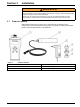
Installation Figure 2 Inserting the rechargeable batteries 1 Catch 4 Battery holder 2 Battery compartment 5 rechargeable Batteries 3 Battery clip 6 Cap 3.2.2 Install the charger WA R N I N G Risk of fire and explosion. Only use the battery charger LZY607 to charge the rechargeable NiMH batteries. 1. Push the slide switch (item 2, Figure 3) on the back of the charger up and remove the adapter (item 3, Figure 3). 2. Fix the required adapter to the charger, until it audibly locks into place.
Installation Figure 3 Replacing the adapter 1 Charger 2 Slide switch 3.2.3 3 Removing the adapter Charging the rechargeable batteries Note: The instrument must be switched off while charging so that the rechargeable batteries can be charged. Note: When using the instrument for the first time, charge for at least three hours. The rechargeable batteries are fully charged when the LED on the charger is green. 1.
Installation Figure 4 Charging the rechargeable batteries 1 Charger 4 Charging socket 2 Discharge button (yellow) 5 LED lamp (green => rechargeable batteries fully charged) 3 Charging plug 6 LED lamp (red => rechargeable batteries currently charging) 3.3 Connecting the probe Remove the protective cap and connect the probe plug to the instrument (Figure 5).
Installation Figure 5 1 Connecting the probe plug to the instrument Probe plug 3.4 2 Probe connection Switching the instrument on and off 1. Fully charge the rechargeable batteries (see section 3.2.3). Note: The rechargeable batteries are fully charged when the LED on the charger is green. 2. Press ENTER/ON for two seconds to turn on the instrument. Note: If the instrument does not turn on, check the position of the rechargeable batteries. 3.
Section 4 4.1 Start Up System start overview 1. Switch on the measurement instrument (section 3.4, page 14). 2. Connect the probe to the measurement instrument (section 3.3, page 13). 3. Edit the time/date, display, units, language and integration time (section 4.3, page 17). 4. Calibration of the solids calibration curve in line with calibration instructions (section 4.7, page 19). 5. Select desired calibration curve (section 4.8, page 19). 6. Show the data in the display (section 5.3, page 27). 4.
Start Up 4.2.2 Display In its basic setting, the display shows the main measurement variables and the date/time (Figure 7). It can be set in a user-defined manner, see section 4.5, page 18. Table 1 Navigating in the menu Navigation key Description Navigation key RIGHT/LEFT Navigation occurs with the RIGHT/LEFT navigation keys. Navigation key UP/DOWN Navigation occurs with the UP/DOWN navigation keys. ENTER/ON – Confirm selection and entry with ENTER/ON. – Switch the instrument on with ENTER/ON.
Start Up 4.2.2.1 Querying internal information Information about the probe and instrument can be queried directly from the main menu using the navigation keys UP/DOWN. The following information is displayed: a. Measurement value (homogeneity in %) b. Battery charge level c. Diagnosis parameters, such as: 4.3 • Probe serial number (instrument information) • Probe software version (instrument information) • Probe number Start XX (probe diagnosis data) • DATA rem. cap.
Start Up 4.5 Setting the display It is possible to custom-define the first two rows of the display. In the standard setting, the first line shows the main measured variable and the second line shows the date/time. 1. Select MENU, confirm with ENTER/ON. 2. Select DISPLAY, confirm with ENTER/ON. 3. Select ROW 1, confirm with ENTER/ON. 4. Select option for ROW 1, confirm with ENTER/ON. • Measurement value • Homogeneous • Battery • Time 5. Select ROW 2, confirm with ENTER/ON. 6.
Start Up 4.7 Calibration For turbidity measurement, a standard curve C-TU is already stored in the probe. Calibration is not required. However, for solids measurement, calibration is required in order to set the rough measurement signals to a calibrated display (refer to section 5.1, page 23). A precise solids measurement is not possible without calibration. There are four calibration curves available: C-DS1, C-DS2, C-DS3, C-DS4. These curves can be allocated to the individual measurement points. 4.8 4.
Start Up Calibrate curve C-DS1: 7. Select MEMORY and confirm with ENTER/ON. 8. Lower the probe into a container that contains a homogeneous sample. 9. Select POINT 1 and confirm with ENTER/ON while stirring the measuring medium with the probe. The distance between the probe head and the walls and base of the container must always be more than 70 mm (2.76 in.). It takes 5 to 20 seconds to record the calibration point; then the selection menu for calibration appears.
Start Up 4.8.2.2 Practical example for turbidity measurement A standard curve C-TU is stored for the turbidity measurement. 1. Connect probe to instrument. 2. To switch the instrument on, press ENTER/ON for 2 seconds. 3. Select READ and confirm withENTER/ON. 4. Place probe in measuring medium. 5. Select START and confirm with ENTER/ON. Note: The data is automatically saved every minute, max. 290 measurement points. 6. To stop the measurement, select READ and confirm with ENTER/ON. 7.
Start Up 22
Section 5 5.1 Operation Calibration Turbidity measurements do not need to be calibrated, as a standardized calibration curve according to ISO 7027 is stored in the instrument. It is possible to create a customer-specific calibration of the turbidity curve. If the standard curve has been altered, a star (*) appears before the measurement point. Solids measurements must be calibrated on site.
Operation 5.1.2 Calibrating The instrument can save one turbidity curve and up to four solids calibration curves. This makes measurements in media with different qualities possible. Each measurement point can have one of the saved calibration curves assigned to it individually. 1-point calibration In order to define a calibration curve, it is generally sufficient to use a single calibration point in the probe's measuring range. This should lie in the upper third of the expected measuring range.
Operation 14. Enter the laboratory values using the navigation keys and confirm with ENTER/ON. • Navigation key LEFT/RIGHT: Jump to the next/previous decimal place • Navigation key UP/DOWN: Change number The laboratory value is saved. The main menu is shown. Repeat steps 1 to 14 to record additional calibration points. The instrument automatically sorts the saved calibration points according to the size of the calibration values.
Operation 5.1.3 Manual calibration value correction 1. Select MENU, confirm with ENTER/ON. 2. Select CALIBRATE, confirm with ENTER/ON. The instrument reads the probe data. 3. Select the curve shown and confirm with ENTER/ON. 4. Select the desired curve and confirm withENTER/ON. 5. Select the desired point and confirm with ENTER/ON. 6. Overwrite the existing calibration point. 7. Enter the value for the calibration point using the navigation keys and confirm with ENTER/ON. 5.1.
Operation 5.2.1 Selecting the calibration curve Before starting the measurement, the calibration curve that corresponds to the measurement point must be selected. 1. Select MENU, confirm with ENTER/ON. 2. Select CALIBRATE, confirm with ENTER/ON. 3. Selectthe curve shown and confirm with ENTER/ON. 4. Select the desired curve with the navigation key UP/DOWN and confirm with ENTER/ON. 5. Select CLEAR/OFF twice to return to the main menu. 5.2.
Operation 5.5 Delete stored data for all calibration curves 1. Select MENU, confirm with ENTER/ON. 2. Select SYSTEM, confirm with ENTER/ON. 3. Enter the value 379 using the navigation keys and confirm with ENTER/ON.
Section 6 Maintenance CAUTION Potential chemical and biological eye and skin hazards. Only qualified personnel should perform the tasks described in this section of the operating manual. The cleanliness of the measurement windows in the sensor head is critical to the accuracy of the measurement results! Cleaning the instrument Clean the instrument with a damp, lint-free cloth. Cleaning the measurement windows The windows are made of sapphire glass.
Maintenance 30
Section 7 7.
Troubleshooting 32
Section 8 Replacement parts and accessories 8.1 Replacement Parts Description Order-No. TSS Portable handheld instrument (TSS Portable handheld measurement instrument includes meter, TSS probe (10 m (32.8 ft) cable, plug), charger with four adapters (ES, USA, GB and AUS/China), rechargeable batteries, manual and carry case LXV322.99.00001 TSS Portable handheld instrument LXV320.99.00001 TSS probe (10 m (32.8 ft) cable, plug) LXV321.99.00001 6× rechargeable NiMH batteries, AA min. 1.
Replacement parts and accessories 34
Section 9 Contact information HACH Company World Headquarters P.O. Box 389 Loveland, Colorado 80539-0389 U.S.A. Tel (800) 227-HACH (800) -227-4224 (U.S.A. only) Fax (970) 669-2932 orders@hach.com www.hach.com Repair Service in the United States: HACH Company Ames Service 100 Dayton Avenue Ames, Iowa 50010 Tel (800) 227-4224 (U.S.A. only) Fax (515) 232-3835 Repair Service in Canada: Hach Sales & Service Canada Ltd.
Contact information HACH LANGE D.O.O. Fajfarjeva 15 SI-1230 Domžale Tel. +386 (0)59 051 000 Fax +386 (0)59 051 010 info@hach-lange.si www.hach-lange.si HACH LANGE OOO Finlyandsky prospekt, 4A Business Zentrum “Petrovsky fort”, R.803 RU-194044, Sankt-Petersburg Tel. +7 (812) 458 56 00 Fax. +7 (812) 458 56 00 info.russia@hach-lange.com www.hach-lange.com 36 ΗΑCH LANGE E.Π.Ε. Αυλίδος 27 GR-115 27 Αθήνα Τηλ. +30 210 7777038 Fax +30 210 7777976 info@hach-lange.gr www.hach-lange.
Section 10 Warranty and liability The manufacturer warrants that the supplied product is free of material and manufacturing defects and undertakes to repair or replace any defective parts at zero cost to the owner. The warranty period is 24 months. If a maintenance contract is taken out within 6 months of purchase, the warranty period is extended to 60 months.
Warranty and liability 38