DOC023.52.90202 RTC101 P-Module Real-Time Control System for Phosphorus Removal User manual 02/2013, edition 4A © HACH-LANGE GmbH, 2010, 2011,2013 All rights reserved. Printed in Germany.
Table of Contents Section 1 Specifications ........................................................................................................................ 5 Section 2 General Information............................................................................................................... 7 2.1 Safety information............................................................................................................................... 7 2.2 Areas of application ..........................
Table of Contents 4
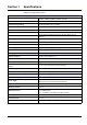
Section 1 Specifications Subject to change without notice.
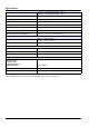
Specifications Digital outputs 1-channel: 1 × for dosing pump and 1 × alarm 2-channel: 2 × for dosing pump and 1 × alarm Nominal load voltage 24 VDC (–15 % / +20 %) Load type Ohmic, inductive, lamp load Max. output current 0.5 A (short-circuit proof) per channel Short-circuit current 0.7 to 1.7 A Reverse polarity protection Yes Electrical isolation 500 Veff (K-bus/field voltage) Power contact current consumption 20 mA typ. (for typ.
Section 2 2.1 General Information Safety information Please read this entire manual before unpacking, setting up, or operating this equipment. Pay attention to all danger and caution statements. Failure to do so could result in serious injury to the operator or damage to the equipment. To prevent damage to or impairment of the device's protection equipment, the device may only be used or installed as described in this manual. 2.1.
General Information 2.2 Areas of application The RTC101 P-Module is a universal open-loop control and closed-loop control unit in waste water treatment plants for automatic precipitant metering for phosphate precipitation. Depending on the operating situation, the precipitant dosage can be based on measured values in the influent or effluent or based on profiles. The system automatically selects the best possible strategy. The user is able to make restrictions manually.
General Information 2.4 Scope of delivery Each RTC101 P-Module is supplied with: • SUB-D connector (9 pin) • Ferrite core, folding • Manual Check that the order is complete. If anything is missing or damaged, please contact the manufacturer or distributor. NOTICE The combination of pre-assembled components supplied by the manufacturer does not represent a standalone functional unit.
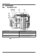
General Information 2.5 Instrument overview Figure 1 Base module RTC 24 V version . 1 PE (protective earth) 5 sc 1000 connection: RS485 (CX1010-N031) 2 24 V 6 Battery compartment 3 0V 7 CPU base module, consisting of Ethernet port with battery compartment (CX1010-N000), CPU module with CF card (CX1010-0021) and passive aeration element. 4 Automatic circuit breaker (ON/OFF switch for item 7 and 8 without fuse function).
General Information Abbildung 2 Base module RTC 100-240 V version 1 L(+) 7 Automatic circuit breaker (ON/OFF switch for item 10 and 11 without fuse function). 2 N(–) 8 sc 1000 connection: RS485 (CX1010-N041) 3 Input AC 100–240 V / Input DC 95 V–250 V 9 Battery compartment 4 PE (protective earth) 10 CPU base module, consisting of Ethernet port with battery compartment (CX1010-N000), CPU module with CF card (CX1010-0021) and passive aeration element.
General Information 12
Section 3 Installation DANGER Only qualified experts may perform the tasks described in this section of the manual, while adhering to all locally valid safety regulations. CAUTION Always lay cables and hoses so that they are straight and do not pose a tripping hazard. CAUTION Before the power supply is switched on, refer to the instructions in the relevant manuals! 3.1 RTC101 P-Module connection The RTC module must be installed on a DIN rail/standard rail.
Installation 3.3.1 PHOSPHAX sc analyzer power supply Refer to the PHOSPHAX sc manual. 3.4 sc1000 controller connection Connect the SUB-D plug supplied to a dual-core, sheathed data cable (signal or bus cable). For further information regarding the data cable connection, refer to the enclosed assembly instructions. 3.5 Flow rate signal connection If a flow rate measurement signal of 4 to 20 mA is available, connect it to the analog input of the RTC module. 3.
Section 4 4.1 Parameterization and operation Open-loop control and closed-loop control programs Four different programs are provided to enable optimal adaptation to local conditions and to the available measurement signals. Programs 3 and 4 have various functions depending on whether open-loop control or closed-loop control is selected. 4.1.1 Open-loop control For the open-loop control of precipitant dosing, the measuring point for phosphate concentration is upstream of the precipitant dosing point. 4.
Parameterization and operation 4.1.2 Closed-loop control according to measured phosphate values For the closed-loop control of the precipitant dosing, the measuring point for the phosphate concentration is downstream of the precipitant dosing point. Program 3 Closed-loop control: • Measured value of the phosphate concentration in the reactor outlet • Specified profile for the flow rate (can be deactivated) Note: The prerequisite for this program is that the PO4-P measurement signal is valid.
Parameterization and operation Figure 3 Program change Q/PO4-P Program 4 Q/PO4-P profile Program 2 Q profile/PO4-P Program 3 Q profile/PO4-P profile Program 1 If both measurement signals become invalid at the same time, the system switches between programs 4 and 1 without intermediate stages. 4.2.2 Manual pre-selection Manual pre-selection limits the selection of programs.
Parameterization and operation 4.3 4.3.1 Parameterization on the sc1000 User interfaces and navigation Before the system is used, the user must be familiar with the sc controller functions. Learn how to navigate through the menu and perform the relevant functions. 4.3.2 System setup 1. Open the MAIN MENU. 2. Select RTC MODULE / PROGNOSYS and confirm. 3. Select the RTC MODULE menu and confirm. 4. Select the RTC module and confirm.
Parameterization and operation 4.3.3 1-channel open-loop control 1-channel open-loop control CONFIGURE SELECT SENSOR Select the sensor installed for the open-loop control (see Section 4.4, page 29). OPEN-LOOP PRECIP. TYPE Precipitation, simultaneous precipitation, post-precipitation SETPOINT PO4-P Desired orthophosphate value in effluent (refer to 4.5.1, page 31) [mg/L] CORR FACTOR Percentage correction of precipitant dosing (see 4.5.
Parameterization and operation 1-channel open-loop control CONFIGURE (CONTINUE) PRECIPITANT METAL CONTENT Metal concentration in precipitant (refer to 4.5.8, page 35) [g/L] ATOMIC WEIGHT Relative atomic weight of active precipitant substance (refer to 4.5.8, page 35) [g/mol] MODBUS ADDRESS Start address of an RTC module within the MODBUS network. Default is 41. This setting must only be changed by the manufacturer's service department (Section 8).
Parameterization and operation 2-channel open-loop control CONFIGURE SELECT SENSOR Select the sensors installed for the open-loop control (see Section 4.4, page 29). OPEN-LOOP PRECIP. TYPE Precipitation, simultaneous precipitation, post-precipitation CHANNEL 1 SETPOINT PO4-P Desired orthophosphate value in effluent (refer to 4.5.1, page 31) [mg/L] CORR FACTOR Percentage correction of precipitant dosing (see 4.5.2, page 31) [%] BIO-P Phosphate biologically eliminated after influent (refer to 4.5.
Parameterization and operation 2-channel open-loop control CONFIGURE (CONTINUE) CHANNEL 2 MIN PUMP RANGE Lower threshold of flow rate range [L/h] MAX PUMP RANGE Upper threshold of flow rate range [L/h] 0/4...20MA Selection of transfer range according to pump input CONTROL CYCLE Control cycle comprising on- and off-time (see 4.5.6, page 33) [s] MIN RUNTIME Minimum on-time of pump (refer to 4.5.
Parameterization and operation 2-channel open-loop control CONFIGURE (CONTINUE) PRECIPITANT CHANNEL 1 METAL CONTENT Metal concentration in precipitant (refer to 4.5.8, page 35) [g/L] ATOMIC WEIGHT Relative atomic weight of active precipitant substance (refer to 4.5.8, page 35) [g/mol] METAL CONTENT Metal concentration in precipitant (refer to 4.5.8, page 35) [g/L] ATOMIC WEIGHT Relative atomic weight of active precipitant substance (refer to 4.5.
Parameterization and operation 4.3.5 1-channel closed-loop control 1-channel closed-loop control CONFIGURE SELECT SENSOR Select the sensor installed for the closed-loop control (refer to Section 4.4, page 29). CLOSED-LOOP SETPOINT PO4-P Desired orthophosphate value in effluent (refer to 4.5.1, page 31) [mg/L] GAIN P CONTR. Proportional gain of the closed-loop control (refer to 4.5.5, page 32) INTEGRALTIME Integral time of closed-loop control (refer to 4.5.
Parameterization and operation 1-channel closed-loop control CONFIGURE (CONTINUE) PRECIPITANT METAL CONTENT Metal concentration in precipitant (refer to 4.5.8, page 35) [g/L] ATOMIC WEIGHT Relative atomic weight of active precipitant substance (refer to 4.5.8, page 35) [g/mol] MODBUS ADDRESS Start address of an RTC module within the MODBUS network. Default is 41. This setting must only be changed by the manufacturer's service department (Section 8).
Parameterization and operation 2-channel closed-loop control CONFIGURE SELECT SENSOR Select the sensors installed for the closed-loop control (see Section 4.4, page 29). CLOSED-LOOP CHANNEL 1 SETPOINT PO4-P Desired orthophosphate value in effluent (refer to 4.5.1, page 31) [mg/L] GAIN P CONTR. Proportional gain of the closed-loop control (refer to 4.5.5, page 32) INTEGRALTIME Integral time of closed-loop control (refer to 4.5.
Parameterization and operation 2-channel closed-loop control CONFIGURE (CONTINUE) IN- OUTPUTS DOSING PUMP CHANNEL 1 MIN PUMP RANGE Lower threshold of flow rate range [L/h] MAX PUMP RANGE Upper threshold of flow rate range [L/h] 0/4...20MA Selection of transfer range according to pump input CONTROL CYCLE Control cycle comprising on- and off-time (see 4.5.6, page 33) [s] MIN RUNTIME Minimum on-time of pump (refer to 4.5.
Parameterization and operation 2-channel closed-loop control CONFIGURE (CONTINUE) PRECIPITANT CHANNEL 1 METAL CONTENT Metal concentration in precipitant (refer to 4.5.8, page 35) [g/L] ATOMIC WEIGHT Relative atomic weight of active precipitant substance (refer to 4.5.8, page 35) [g/mol] METAL CONTENT Metal concentration in precipitant (refer to 4.5.8, page 35) [g/L] ATOMIC WEIGHT Relative atomic weight of active precipitant substance (refer to 4.5.
Parameterization and operation 4.4 Select sensors 1. To select the sensors and their sequence for the RTC module, press RTC > CONFIGURE > SELECT SENSOR. Figure 4 Select sensor 1 ENTER — Saves the setting and returns to the CONFIGURE menu. 4 DELETE — Removes a sensor from the selection. 2 CANCEL — Returns to the CONFIGURE menu without saving. 5 UP/DOWN — Moves the sensors up or down. 3 ADD — Adds a new sensor to the selection. 2. Press ADD (Figure 4, item 3).
Parameterization and operation 4. The selected sensor is shown in the sensor list. Press ADD (Figure 4, item 3) to open the selection list again. 5. Select the second sensor for the RTC module and confirm by pressing ENTER below the selection list. Note: Previously selected sensors are shown in gray. The selected sensors are shown in the sensor list. 6. To sort the sensors in the order specified for the RTC module, press the sensor and use the arrow keys to move it (Figure 4, item 5).
Parameterization and operation 4.5 4.5.1 Explanations Ortho-phosphate and total phosphate The goal of phosphate control is to reduce the total phosphate in the effluent stream at a waste water treatment plant. However, the precipitation only affects the ortho-phosphate content. The PO4-P target value specifies the ortho-phosphate value to be maintained in the precipitation reactor. Therefore, this value must be lower than the value to be maintained in the effluent.
Parameterization and operation 4.5.4 Phosphate profile The same conditions as specified under 4.5.3, page 31 must apply for the phosphate flow rate profile. If biological phosphate elimination is still not effective at the measuring point, the flow profile rate remains unaffected by the biological phosphate elimination. If biological phosphate elimination is already effective at the measuring point, this must also be reflected in the profile.
Parameterization and operation Example: A derivative time of 1 minute means that closed-loop control takes place according to the phosphate concentration that is actually achieved in only 1 minute (if the current measured value change remains the same). The integration time takes effect by means of the temporal integration of the control deviation (PO4-P setpoint to PO4-P actual value), to the actuating variable with the weighting by the INTEGRALTIME.
Parameterization and operation 4.5.7 Inclusion of return sludge quantity To be able to record the entire flow at the measuring point, the return sludge quantity must also be taken into account, depending on the specific application. For this purpose, the minimum and maximum flow rate of the return activated sludge pump(s) can be specified, as well as the ratio of return activated sludge transport relative to the measured flow rate. The flow rate, e.g.
Parameterization and operation With the setting Q INFLUENT SMOOTH = 2, it takes three minutes for the smoothed value to reach 95 % of the final value (following a sudden change of the influent rate). 4.5.8 Precipitants For calculations, the effective metal content of the precipitant must be specified in g/l as well as the relative atomic weight of the metal in g/mol. 4.5.8.1 Metal content The metal content (active component) of the precipitant is specified by the manufacturer in: 4.5.8.
Parameterization and operation Molar metal concentration for a compound of iron (12 %) and aluminum (8 %): 2.79 mol + kg 2.15 mol kg = 5.12 mol kg A conversion is performed with the product density for entry in the RTC module: 1.43 kg L × 5.12 mol kg = 7.32 mol L The product of the molar concentration [mol/kg] and the density of the product [kg/L] yields the molar metal concentration in mol/L. As stated above, this numerical value must be entered for the metal content.
Section 5 Maintenance DANGER Multiple hazards Only qualified personnel must conduct the tasks described in this section of the manual. 5.
Maintenance 38
Section 6 6.1 Troubleshooting Error messages The sc controller displays the possible sensor errors.
Troubleshooting 40
Section 7 7.1 Replacement parts and accessories Spare parts Description Cat. no. NS 35/15 DIN rail, punched according to DIN EN 60715 TH35, made from galvanized steel. Length: 35 cm (13.7 in) LZH165 90–240 V AC/24 V DC 0.
Replacement parts and accessories 42
Section 8 Contact information Repair Service in the United States: HACH Company Ames Service 100 Dayton Avenue Ames, Iowa 50010 Tel (800) 227-4224 (U.S.A. only) Fax (515) 232-3835 Repair Service in Canada: Hach Sales & Service Canada Ltd. 1313 Border Street, Unit 34 Winnipeg, Manitoba R3H 0X4 Tel (800) 665-7635 (Canada only) Tel (204) 632-5598 Fax (204) 694-5134 canada@hach.
Contact information HACH LANGE D.O.O. Fajfarjeva 15 SI-1230 Domžale Tel. +386 (0)59 051 000 Fax +386 (0)59 051 010 info@hach-lange.si www.hach-lange.si HACH LANGE OOO Finlyandsky prospekt, 4A Business Zentrum “Petrovsky fort”, R.803 RU-194044, Sankt-Petersburg Tel. +7 (812) 458 56 00 Fax. +7 (812) 458 56 00 info.russia@hach-lange.com www.hach-lange.com 44 ΗΑCH LANGE E.Π.Ε. Αυλίδος 27 GR-115 27 Αθήνα Τηλ. +30 210 7777038 Fax +30 210 7777976 info@hach-lange.gr www.hach-lange.gr HACH LANGE D.O.O.
Section 9 Warranty and liability The manufacturer warrants that the supplied product is free of material and manufacturing defects, and undertakes to repair or to replace any defective parts without charge. The warranty period is 24 months. If a maintenance contract is taken out within 6 months of purchase, the warranty period is extended to 60 months.
Warranty and liability 46
Appendix A MODBUS address setting The same slave address for MODBUS communication must be set on both the sc1000 display and on the RTC101 P-Module. As 20 slave addresses are reserved for internal purposes, the following slave addresses are available for assignment: 1, 21, 41, 61, 81, 101 etc. Slave address 41 is preset at the factory.
MODBUS address setting 48