
Sigma 900 MAX Refrigerated Sampler Instrument Manual


Page 102
Circuit Board Identification
8990mnt.fm
Section 7
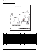
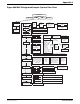
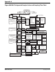
Figure 32 Utility Board
Table 21 Utility Board Connections
ID Description ID Description
J1 Distributor J12 Analog Input Channel 5
J2 Auxiliary J13 Analog Input Channel 6
J3 pH/ ORP J14 Analog Input Channel 7
J4 CPU Board J15 Thermal Control
J5 Rain Gauge J16 12 V dc Main
J6 Bubbler Module J17 Relay Output
J7 Fluid Sensor #1 J18 4–20 mA PCB
J8 Analog Input Channel 1 J19 Fluid Sensor #2 (closest to pump)
J9 Analog Input Channel 2 J20 D.O. / Conductivity
J10 Analog Input Channel 3 J21 Submerged Sensor
J11 Analog Input Channel 4 J22 5 amp External Fuse
UTILITY BOARD
J19
J7
J5
J1
J2
J20
J21
J17
J6
J18
J3
J15
J22
C11
TB1
J16
J4
J8
J9
J10
J11
J12
J13
J14
F2