
Sigma 900 MAX Refrigerated Sampler Instrument Manual


Section 1
Page 19
8990int.fm Principle of Operation
1.4 Principle of Operation
1.4.1 Liquid Sensing
The sampler is designed for indoor, permanent installation. All controls are
located on the front panel. Capped, watertight connectors for interfacing to
external devices are located along the left side of the controller.
The sampler uses a liquid sensing system to detect the absence or presence
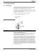
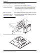
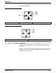
of liquid at the peristaltic pump intake. The liquid sensor (Figure 3) is located
on the front of the control housing.
The liquid sensing system provides three primary benefits:
• Accurate, repeatable sample volumes
• Intake tube prerinse
• Sample retry
Figure 3 Liquid Sensor
Accurate, Repeatable Sample Volumes
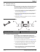
The liquid sensor detects the presence and velocity of the incoming sample.
This information allows the sampler to automatically dispense the correct
amount of liquid into the sample bottle.
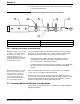
The liquid sensing system allows the sampler to deliver repeatable sample
volumes even with changing suction lifts. Each time the peristaltic pump pulls
a sample, the microprocessor determines the time required for liquid to travel
to the liquid sensor. If the suction lift increases due to a drop in level at the
sample source, the time required for liquid to reach the sensor will increase.
The microprocessor automatically compensates for this change by allowing
the peristaltic pump to deliver sample liquid for a corresponding longer period
of time. Conversely, if suction lift decreases due to an increase in level at the
sample source, the time required for liquid to the sensor will decrease. Again,
the microprocessor automatically compensates for this change by decreasing
the sample delivery time.
1. Sensor Body 2. Sensor Cover 3. Knobs (turn to remove)
2
1
3