
Sigma 900 MAX Refrigerated Sampler Instrument Manual


Page 70
pH Probe
8990options.fm
Section 5
5.1.1 Rain Gauge Programming
1. From the Main Menu select OPTIONS>ADVANCED OPTIONS>DATALOG.
2. Highlight Select Inputs using the UP and DOWN keys and press SELECT.
Note: When logging is enabled, an
arrow will point to the logged
channel.
3. Highlight Rainfall using the UP and DOWN keys and press SELECT.
4. Press the
CHANGE CHOICE key to cycle between Logged and Not
Logged, then press
ACCEPT.
5. Enter a logging interval using the numeric keypad, then press
ACCEPT.
Valid logging intervals are shown on the status bar along the bottom edge
of the display.
6. Select Rainfall Units (in. or cm).
7. Select another channel to configure, or press
RETURN to back up one
step. Press the
MAIN MENU key to return to the Main Menu.
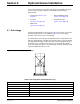
5.2 pH Probe
The pH probes are shipped with a wetting cap that covers the probe tip.
Remove the cap by turning it counter-clockwise and gently easing it off. Keep
this cap for long-term probe storage. Rinse the probe tip with distilled water.
Store the probe in a pH 4.0 buffer (Cat. No. 2104) for both overnight and long
term storage. Never store a probe in distilled or deionized water because this
will deplete the probe filling solution.
5.2.1 pH Probe Connection
This connector is for installing the pH or ORP pre-amp interface junction box
or a stand-alone temperature sensor. The pH probe is attached to a terminal
strip in the junction box. The stand-alone temperature probe plugs directly into
the receptacle on the case.
The pre-amplifier junction box is provided to allow for fast, easy replacement
of the pH probe.
Since the pH reading needs to compensate for temperature variation, a
temperature sensor is built into every pH electrode. The pH probe consists of
five wires, three for the pH probe and two for the temperature sensor.
Stray electrical currents are sometimes found in wastewater stream. These
stray electrical currents can affect the pH readings. In the case of stray
electrical currents, a grounded pH probe is required. See Figure 22.
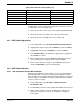
Table 8 pH Connector Pin Assignments (J3)
Pin Signal Description Wire Color
A+5 V dc White
B ground Blue
C reference Yellow
DpH/ORP Black
E -5 V dc Red
FRTD Green