
Sigma 900 MAX Refrigerated Sampler Instrument Manual


Section 5
Page 73
8990options.fm ORP Probe
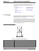
The ORP probe consists of three wires; a pink, black, and red wire. There is
no temperature sensor on the ORP probe.
1. Attach the clear wire to either screw on the terminal strip labeled GLASS.
2. Attach the black wire to the REF screw on the other terminal strip.
3. Attach the red wire to the GND screw on the terminal strip.
5.3.2 ORP Probe Programming
1. From the Main Menu, select OPTIONS>ADVANCED OPTIONS>DATALOG.
2. Highlight Select Inputs using the UP and DOWN keys and press SELECT.
3. Highlight ORP using the
UP and DOWN keys, then press SELECT.
4. Press
CHANGE CHOICE to cycle between Logged and Not Logged, then
press
ACCEPT to continue.
5. Enter a logging interval, then press
ACCEPT. Valid logging intervals are
shown on the status bar along the bottom edge of the display.
6. Select another channel to configure or press
RETURN to back up one
step. Press
MAIN MENU to return to the Main Menu.
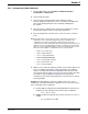
5.3.3 ORP Probe Calibration
5.3.3.1 ORP Preamplifier/Junction Box Calibration
Calibration of the ORP input circuit requires a source of dc voltage between
500 and 2000 m V dc. The reference voltage must be applied to the ORP
input terminals on the preamplifier/junction box during calibration. A regulated
dc power supply or a standard “C” cell battery (1500 mV dc) make excellent
sources for reference voltage.
1. From the Main Menu, select
OPTIONS > ADVANCED OPTIONS >
CALIBRATION > ORP.
2. Install the ORP junction box on the sampler with the ORP probe removed.
3. Apply a positive reference voltage to the ORP probe terminals in the
junction box, using either a 1.5 V dc “C” cell battery or a regulated
power supply.
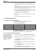
Table 9 ORP Connector Pin Assignments (J3)
Pin Signal Description Wire Color
A+5 V dc White
B ground Blue
C reference Yellow
DpH/ORP Black
E5 V dc Red
FRTD Green