
Sigma 900 MAX Refrigerated Sampler Instrument Manual


Page 74
Dissolved Oxygen Probe
8990options.fm
Section 5
4. Attach the positive battery terminal to the terminal block screw labeled
“glass” and the negative battery terminal to the terminal block screw
labeled “ref.”
5. After making all connections, measure the exact voltage on the “C” cell or
power supply with a voltmeter. Then press a key to continue. The sampler
displays the message “Waiting for ORP to Stabilize.”
6. Once the reading is sufficiently stable enter a new millivolt level. The “C”
cell battery should be approximately 1500 mV (or 1.5 V) when new. Enter
the exact voltage of the current source in millivolts.
7. Press
ACCEPT to store the new calibration values.
8. Disconnect the “C” cell battery or regulated power supply from the ORP
input terminals.
9. Reconnect the ORP Probe leads to the input terminals.
5.4 Dissolved Oxygen Probe
5.4.1 Dissolved Oxygen Probe Connection
This connection is for interfacing the optional D.O. probe to the
D.O./Conductivity Pre-Amp (Cat. No. 3369).
Strain Relief Recommendation
A strain relief is recommended to protect the cable/probe junction during
application where the sensor will be thrown or tossed into liquid.
5.4.2 Dissolved Oxygen Probe Programming
Note: The membrane thickness
must be programmed into the
instrument. The instrument uses
this information to determine if the
sensor is generating a reasonable
current. Failure to program this
value may result in false error
conditions
1. From the Main Menu, select OPTIONS>ADVANCED OPTIONS>DATALOG.
2. Highlight Select Inputs using the UP and DOWN keys and press SELECT.
3. Highlight D.O. using the
UP and DOWN keys, then press SELECT.
4. Press
CHANGE CHOICE to cycle between Logged and Not Logged, then
press
ACCEPT.
5. Enter a logging interval, then press
ACCEPT. Valid logging intervals are
shown on the status bar.
6. Press
CHANGE CHOICE to select the appropriate units (ppm, ppb, mg/L,
sat). Press
ACCEPT to continue.
7. Select another channel to configure, press
RETURN to back up one step
or press
MAIN MENU to return to the Main Menu.
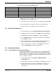
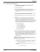
Table 10 D.O. Connections (J20)
Pin Signal Description Wire Color
A DO - (neg) Green
B DO + (pos) Red
C Thermister Black
D Thermister Yellow