
Sigma 900 MAX Refrigerated Sampler Instrument Manual


Section 6
Page 87
8990cm.fm 4–20 mA Option
6.3 4–20 mA Option
The 4–20 mA option provides a current loop for controlling external devices
such as a chart recorder or PC. Either one or both of the 4–20 mA outputs can
be factory installed and are isolated from each other.
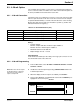
6.3.1 4–20 mA Connection
The interface has a 3-ft cable with a connector on one end, and a 10-ft cable
with two open wire leads on the other. Insert the connector into the sampler
receptacle labeled “Auxiliary”, located on the left side of the control housing.
On the 10-ft cable, the wire with clear insulation is positive (+) and the wire
with black insulation is negative (-).
Rating:
• Isolation Voltage:
Between sampler and either 4–20 mA output: 2500 V ac
Between the two 4–20 mA outputs: 1500 V ac
• Maximum Resistive Load: 600 ohm
• Output Voltage: 24 V dc - no load
Cable Required
4–20 mA Interface Cable (Cat. No. 2924), 25 ft long, 4-pin connector on one
end, tinned wire leads on the other end.
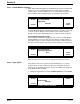
6.3.2 4–20 mA Programming
1. From the Main Menu, select OPTIONS > ADVANCED OPTIONS > 4–20 mA
OUTPUTS > SELECT
.
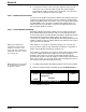
Note: When the 4–20 mA outputs
are disabled and not completely
turned off, they will continue to
output a steady 4 mA.
2. Enable the 4–20 mA outputs by pressing CHANGE CHOICE while in the
4–20 mA output menu.
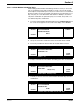
3. When the display shows the outputs as enabled, press
ACCEPT.
4. Choose either OUTPUT A or OUTPUT B. Use the
UP and DOWN keys to
highlight the choice, then press
SELECT.
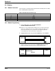
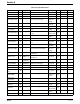
Table 16 4–20 mA Connections (J18)
Pin Signal Description Wire Color
A Output 1 + (pos) Yellow
B Output 1 - (neg) Black
C Output 2 + (pos) Red
D Output 2 - (neg) Green
11:00 AM 21 - APR - 01 4–20 mA OUTPUTS
SELECT
OUTPUT A
OUTPUT B
RETURN