
Sigma 900 MAX Refrigerated Sampler Instrument Manual


Page 88
4–20 mA Option
8990cm.fm
Section 6
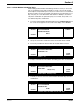
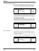
5. Select an analog Input Channel (e.g., channel 1, 2, 3, or, flow, etc.) to
assign to that output. Press
CHANGE CHOICE to cycle through the
channel names. When the desired channel is displayed, press
ACCEPT.
6. Assign a channel value to the 4 mA current value. This value is typically 0,
however any value can be set. Enter the value of the input needed to
generate 4 mA of current at the output.
7. Assign an input value to the 20 mA current level.
8. Repeat this process to configure the other 4–20 mA output.
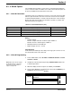
6.3.3 4–20 mA Calibration
After wiring the 4–20 mA connection perform a 4–20 mA output calibration.
The 4–20 mA output calibration requires a digital multimeter or access to the
4–20 mA current loop wiring. Two 4–20 mA outputs are available and are
designated Output A and Output B. Both outputs are calibrated the same way
and are isolated from each other.
Calibration may be performed while the 4–20 mA device is in the current loop,
as shown in Figure 24 or disconnected from the current loop as shown in
Figure 25. In either case, the multimeter must be set to a 20 milliamp dc range
or greater.
1. From the Main Menu, select
OPTIONS > ADVANCED OPTIONS >
CALIBRATION > 4–20 mA OUTPUTS.
2. Connect a multimeter to the 4–20 mA current outputs per Figure 24 and
Figure 25.
3. Make sure that the 4–20 mA output is enabled. If it is not enabled, press
CHANGE CHOICE so that the display shows Enabled and press ACCEPT.
4. Select the output (A or B) to calibrate.
5. Press any key to set the selected output to 4.00 mA dc.
6. Measure the current on the selected output using the multimeter and
enter the measured value using the numeric keypad. Press
ACCEPT.
11:00 AM 21 - APR - 01 4–20 mA OUTPUTS
ACCEPT
CHANGE
CHOICE
INPUT CHANNEL:
CANCEL
FLOW
SELECT APPROPRIATE UNITS
11:00 AM 21 - APR - 01 4–20 mA OUTPUTS
ACCEPT
4 mA INPUT VALUE
CLEAR
ENTRY
0.00 mgd CANCEL
SELECT APPROPRIATE UNITS