
Sigma 900 MAX Refrigerated Sampler Instrument Manual


Section 6
Page 89
8990cm.fm Alarm Relays
7. Press any key to set the output to 20.00 mA dc.
8. Measure the current on the selected output using the multimeter and
enter the measured value using the numeric keypad. Press
ACCEPT to
complete the calibration.
By entering the measured current values, the microprocessor will
electronically adjust the outputs to compensate for the difference between the
measured values and the expected values.
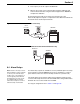
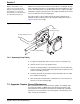
Figure 24 Calibration with the Meter in the Loop
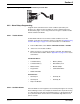
Figure 25 Calibration with the 4–20 mA Device Disconnected from the Loop
6.4 Alarm Relays
Note: Current to the relay contacts
must be limited to 5 amps. A means
to remove power from the relays
locally in case of an emergency or
for servicing the product must be
provided by the user. This can be
accomplished with an external
switch and a 5-amp fuse or with a
switched 5-amp circuit breaker.
Four alarm relay outputs are available as a factory installed option. The relays
are mounted in an external NEMA 4X enclosure for installation to a wall or
panel. Alarm contacts are rated for 10 amps at 240 V ac (resistive load).
The alarm wiring can be sized according to the load being used. The relay
connector will accept wire sizes from 18–12 AWG with a rating of 300 V, 80 °C
minimum. Do not use wire smaller than 18 AWG.
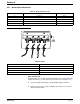
For relay pin assignments refer to Table 17 and Figure 26.
Chart
Recorder
Multimeter
900 MAX
Current Loop
Multimeter
900 MAX