DOC023.53.90007 sc1000 controller USER MANUAL April 2008, Edition 1 © Hach Company, 2008. All rights reserved. Printed in the U.S.A.
Table of Contents Section 1 Specifications .................................................................................................................... 5 Section 2 General Information ......................................................................................................... 9 2.1 Safety information ........................................................................................................................ 9 2.1.1 Use of hazard information...................................
Table of Contents 5.2 The measured value display ......................................................................................................55 5.2.1 Daily and weekly trend lines ..............................................................................................56 5.2.2 Configure the measured value display ..............................................................................56 5.3 The Graph display ................................................................................
Table of Contents 6.3.7 Display settings............................................................................................................... 115 6.3.8 Browser access............................................................................................................... 116 6.3.9 Storage card ................................................................................................................... 116 6.3.10 Security setup ...........................................................
Table of Contents 4
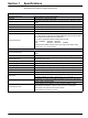
Section 1 Specifications Specifications are subject to change without notice.
Specifications Plug-in Expansion Cards Component description Plug-in expansion cards for installation in the probe module Operating temperature –20 to 55 °C (–4 to 131 °F); 95% relative humidity, non-condensing Storage temperature –20 to 70 °C (–4 to 158 °F); 95% relative humidity, non-condensing Analog output card 4 x analog current outputs (0–20 mA or 4–20 mA, max. 500 Ohm) Terminals max. 1.5 mm2 (AWG15) Analog/digital input card 4 x analog/digital inputs (0–20 mA or 4–20 mA) Terminals max. 1.
Specifications Certifications North America sc1000 with system components - cTUVus to UL 61010-1 & CAN/CSA 22.2 No. 61010-1 sc1000 with GSM Module - FCC ID No. QIPMC56 - Industry Canada ID No. 267W-MC56 Europe sc1000 with system components: - CE Conforms to LV-Directive 2006/95/EC, EMC-Directive 2004/108/EC - TUV-GS to EN61010-1 sc1000 with GSM Module: - CETECOM ICT GmbH Registration No.
Specifications 8
Section 2 General Information The information in this manual has been carefully checked and is believed to be accurate. However, the manufacturer assumes no responsibility for any inaccuracies that may be contained in this manual. In no event will the manufacturer be liable for direct, indirect, special, incidental or consequential damages resulting from any defect or omission in this manual, even if advised of the possibility of such damages.
General Information 2.1.2 Precautionary labels Read all labels and tags attached to the instrument. Personal injury or damage to the instrument could occur if not observed This symbol, if noted on the instrument, references the instruction manual for operation and/or safety information. This symbol, when noted on a product enclosure or barrier, indicates that a risk of electrical shock and/or electrocution exists. This symbol, if noted on the product, indicates the need for protective eye wear.
Section 3 Installation DANGER Electrocution hazard. Only qualified personnel should conduct the tasks described in this section of the manual. 3.
Installation 3.1.
Installation 3.2 Mounting the controller 3.2.1 Wall mounting Leave a minimum of 5 cm (2 in.) of space at the top and sides for cooling purposes and display module installation. Leave a minimum of 15 cm (6 in.) of space underneath for the cable connections. Refer to Figure 3 for proper wall mounting dimensions. 1. Install four bolts into the wall. 2. Hang the sc1000 controller over the bolts and attach the supplied washers and hand-tighten the two bottom bolts.
Installation 3.2.2 Vertical or horizontal pipe mounting Refer to Figure 4 for mounting descriptions. For more information on pipe mounting refer to the instructions supplied with the mounting kit. Figure 4 Pipe mounting hardware 1 Bracket, pipe mount (LZY001) 3 Flat washer (4x) (LZX948) 2 Rubber pads (8x) (LZX948) 4 Hexagon head screw (4x) M5 x 30 mm (LZX948) 3.2.3 Panel Mounting Refer to the instruction sheet supplied with the mounting hardware for installation instructions. 3.2.
Installation Figure 5 Remove display module and probe module cover 1 Probe module cover 3 Connector, display module 2 Display module 4 Screw (4x) 3.3.1 Electrostatic discharge (ESD) considerations Important Note: To minimize hazards and ESD risks, maintenance procedures not requiring power to the analyzer should be performed with power removed. Delicate internal electronic components can be damaged by static electricity, resulting in degraded instrument performance or eventual failure.
Installation 3.4 Electrical installation DANGER Electrocution hazard. Only qualified personnel should conduct the installation tasks described in this section of the manual. DANGER Electrocution hazard. Always install a ground fault interrupt circuit (GFIC)/ residual current circuit breaker (rccb) with a maximum trigger current of 30 mA. If installed outside, provide overvoltage protection. If installed outdoors, provide overvoltage protection between the power and the sc1000 controller.
Installation 3.4.2 Installation using a power cord A sealing-type strain relief to maintain the IP65 environmental rating and a power cord less than 3 meters (10 feet) in length with three 18-gauge conductors (including a safety ground wire) can be used, see Section 9 on page 129. See Figure 6 for strain relief and conduit opening sealing plug assembly. See Figure 14 on wiring information.
Installation Figure 8 Removing the probe module cover 1 Ground screw 2 Ground wire 1 High voltage barrier 3 Probe module cover Figure 9 Removing high voltage barrier 18 2 Screw (6x)
Installation Figure 10 Wiring for power 1 AC power connections 3 Ferrite will fit snugly in this area 2 Earth Ground Connections 4 Barrier should fit easily into position 19
Installation Figure 11 Inside the AC probe module 1 Fan 7 Fuse (2x), F3 and F4: T 8A; 100–240 V, slow-blow 2 Main circuit board 8 AC power connections 3 Connector for expansion slot 9 Earth ground connection 4 Connector for expansion slot 10 Power outlet connection 5 Connector for expansion slot 11 Probe connections 6 Fuse (2x), F1 and F2: M 3.5A, medium blow 12 Relay card connection 3.4.3 Wiring for AC power at the controller DANGER Electrocution hazard.
Installation 6. Strip the cable outer insulation 260 mm (10 in.) (Figure 12). Shorten all wires except the earth wire 20 mm (0.78 in.), so the earth cable is 20 mm (0.78 in.) longer than the other cables. 7. Feed the stripped power cable through the ferrite core twice (Figure 12) and wire into the terminal as shown in Table 1 and Figure 10. Tug gently after each insertion to make sure that the connection is secure. 8. Seal any unused openings in the controller box with conduit opening sealing plugs. 9.
Installation Figure 13 Hard-wired installation 1 Ferrite core (Electromagnetic interference device) 3 Earth ground connection 2 AC power connections (optional, LZX970) 4 Conduit hub, strain relief 22
Installation Figure 14 Installation with power cord 1 Ferrite core (Electromagnetic Interference Device) 3 Earth ground connection 2 AC power connections 4 Strain relief 23
Installation 3.4.4 Wiring for 24 VDC power at the controller Important Note: The AC power outlets cannot be used with the 24 VDC power supply. Figure 15 Inside the 24 VDC probe module 1 Fan 6 Fuse, T 6.
Installation Figure 16 Wiring for 24 VDC power 1 24 VDC power terminal block 2 Cable 3 Table 2 Terminal number Strain relief DC power wiring information Terminal description Wire color code for North America Wire color code for Europe + +24 VDC Red Brown - 24 VDC Return Black Blue Protective Earth (PE) Green Green w/yellow tracer 25
Installation 3.5 DIN rail expansion modules CAUTION The expansion modules for control cabinet installation use the 24 VDC power supply in the control cabinet. Make sure that the correct power supply is provided. Install a residual current circuit breaker. The modules have an environmental rating of IP20 and must always be mounted in an enclosure suitably rated for power and environment. The sc1000 controller can be expanded with DIN rail expansion modules.
Installation 3.6 Expansion cards The sc1000 controller can be expanded with internal plug-in expansion cards. Each expansion component can be identified with its serial number on the sc1000 network and programmed as required. The serial number is located on the card. It may be necessary to remove an existing expansion card, if the expansion card is blocking access to certain connectors. Refer to section 3.6.6 on page 37 for more information.
Installation Figure 18 Expansion card ports 1 Relay card 6 mA output or input wiring information 2 Relay wiring information 7 mA output or input card 3 Field-bus or mA output or input card 8 mA output or input wiring information 4 Field-bus or mA output or input card wiring information 9 Main high voltage barrier 5 mA output or input card 10 Relay voltage barrier 3.6.1 Relay card connections DANGER Electrocution hazard. Relays must either be wired as low or high voltage.
Installation To make a relay card connection For instruments not equipped with a relay card, do the steps listed below to make relay card connections. 1. Remove power from the instrument. Remove the probe module cover. 2. Remove the screws on the plastic relay cover. Remove the plastic cover. 3. Connect the relay card to the appropriate slot (Figure 18). Use a magnetic screwdriver to secure the four phillips-head screws to the card.
Installation Table 3 Relay card (YAB022, normally closed) terminal assignments Terminal 1 2 3 4 5 6 7 8 Designation Relay 1–4 Maximum switching voltage: 250 VAC; 125 VDC Maximum switching current: 250 VAC, 5A 125 VAC, 5A 30 VDC, 5A Maximum switching power: 1500 VA 150 W Relay 1 (normally closed contacts) Relay 2 (normally closed contacts) Relay 3 (normally closed contacts) Relay 4 (normally closed contacts) Figure 21 Relay card (YAB076, change over) 1 Conductor (Pull to remove from the board, when wiri
Installation Table 4 Relay card (YAB076, change over) terminal assignments Terminal Designation 1 Relay 1 (normally closed contacts) 2 Relay 1 (common) 3 Relay 1 (normally opened contacts) 4 Relay 2 (normally closed contacts) 5 Relay 2 (common) 6 Relay 2 (normally opened contacts) 7 Relay 3 (normally closed contacts) 8 Relay 3 (common) 9 Relay 3 (normally opened contacts) 10 Relay 4 (normally closed contacts) 11 Relay 4 (common) 12 Relay 4 (normally opened contacts) Relay 1–4 Maxi
Installation Figure 22 Input card (YAB018) cable connections and jumper setting 1 Jumper switches Digital input=Jumper closed Analog input=Jumper opened 2 Terminal block– Refer to Table 5 for terminal assignments.
Installation 3.6.3 Output card connections If the instrument is equipped with the output card option, the mA output card supplies up to 4 analog (0–20 mA/4–20 mA) signals into an impedance of max. 500 Ohm. Note: The sc1000 mA output card cannot be used to provide power to a 2-wire (loop-powered) transmitter. To make an output card connection: 1. Remove power from the instrument. Remove the probe module cover. 2. Connect the output card to the appropriate slot (Figure 18).
Installation 3.6.4 Modbus card connections Modbus RS485 (YAB021) and Modbus RS232 (YAB047) are available. For more detailed information refer to the bus system manual. To make a Modbus card connection: 1. Remove power from the instrument. Remove the probe module cover. 2. Connect the Modbus card to the appropriate slot (Figure 18). Use a magnetic screwdriver to secure the four screws to the card. 3. Install the card connector to the appropriate connection on the main circuit board (Figure 17). 4.
Installation Figure 25 Modbus RS232 (YAB047) card connections 1 Terminal Block (Refer to Table 8 for terminal assignments) Table 8 Modbus RS232 card (YAB047) terminal assignments Terminal Modbus RS232 designation 1 Not Used 2 Ground 3 Not Used 4 TXD (Transmitting line Modbus Card) 5 Not Used 6 RXD (Receiving line Modbus Card) 7 Not Used 3.6.5 Profibus DP card connections Refer to the documentation supplied with the Profibus DP card for more information.
Installation After installation and connection of a plug-in expansion card, the card must be configured to the system. For Profibus card setup instructions refer to section 6.3.4.1 on page 109. Figure 26 Profibus DP card (YAB020) connections 1 Network termination activated, last device on network 2 Network termination deactivated, other devices on network after this device. 3 Terminal Block – Refer to Table 9 for terminal assignments.
Installation 3.6.6 Remove/Replace an expansion card It may be necessary to remove an existing expansion card if probe connectors are obstructed. Important Note: The compact connectors are a very tight fit and the connections can easily break off. Do not apply excessive force when fitting and removing the compact connectors. To remove/replace an expansion card: 1. Delete the card in the sc1000 controller. Refer to section 6.3.6 on page 115. 2. Remove power from the instrument. Remove the probe module cover.
Installation Figure 28 Plugging the network connector to the network interface 1 Probe module 3 sc1000 network connector 2 sc1000 network interface 4 sc1000 network interface cover 3.7.1 sc1000 network connections To attach a network connector: 1. Strip the insulation from the communication cable (Figure 29). 2. Feed the cable through the union nut, rubber seal, and connector housing (Figure 31). 3. Connect the cable to the network connector circuit board as shown in Table 10.
Installation 9. If necessary, set the terminating resistor. Note: When using the connector with the last module on the network segment, one union nut remains unused. Seal the union nut with the plug supplied. Refer to Figure 31. 10. If this connector is the end of the network, insert the rubber seal in the connector. 11. Tighten the union nut by two turns. 12. Insert the sealing plug in the unused union nut and rubber seal. 13. Tighten the union nut. 14.
Installation Figure 30 Network connector components 1 Housing, network connector 7 Insert, plastic label (network connector housing) 2 Network connector printed circuit board with shell bottom 8 Not used 3 Shell, top 9 Plug, rubber, cord grip 4 Screws, self-tapping (2x) 10 Seal, cord grip (2x) 5 Clamp, network cable(s) 11 Cord grip (2x) 6 Screw, pan head 40
Installation Figure 31 Connecting the network connector to the sc1000 network terminating resistor 1 Shell, bottom 6 Housing, network connector 2 Network connector printed circuit board with shell bottom 7 Seal, cord grip 3 Clamp, network cable(s) 8 Cord grip 4 Screw, pan head 9 Plug, rubber, cord grip2 5 Cables, network1 10 Screws, self-tapping (2x) 1 Route 2 Use cables as shown and make sure that clamp is fastened securely.
Installation Figure 32 Setting a terminating resistor (DIP switch in the connector) 1 Housing, network connector 3 Dip switch (note position assignments as shown) 2 Cap, rubber 4 Insert, plastic label Table 11 Communication connector terminating resistor (communication termination) Switch setting Terminating resistors Connection 2 On Enabled Disabled Off Disabled Enabled Note: The DIP switch can also be operated when the connector is fitted.
Installation 3.8 Connect probes to the sc1000 controller All sc series probes can be used on the sc1000 controller. Important Note: Plan the route for the probe cable and lay the data and power cables so that they do not cause a trip hazard and the cables do not have any sharp bends. For details on the installation and operation of the probe, refer to the appropriate probe manual. 3.8.1 Connect the probe data cable 1. Unscrew the protective cover on the controller socket (Figure 33).
Installation 3.8.2 Add probe connections When all probe connectors on the sc1000 controller are already in use for probes, more probe connectors can be added (max. 8 probe connectors). It may be necessary to remove an existing expansion card if accessibility to probe connectors is obstructed (refer to section 3.6.6 on page 37). Note: If a probe module has the maximum number of probes, more probes may be added to the system by purchasing additional probe modules. To add probe connections: 1.
Installation 3.10 GSM modem connection The display module can optionally contain a built-in tri-band modem (Figure 7). The GSM modem connection allows fully remote operation of the sc1000 controller, including transfer of data and software updates.
Installation • Do not expose the equipment to strong vibrations or impacts. • The GSM/GPRS modem can cause disturbances when in the proximity of television sets, radios or PCs. • Do not open the GSM/GPRS modem. Any change of the equipment is inadmissible and leads to the loss of the operating permission. • This unit is to be installed by a trained technician employing proper installation practices for a Radio Frequency Transmitter, including proper grounding of any external antennas.
Installation 3.10.3 Insert the SIM card into the display module Important Note: The touch screen is scratch sensitive. Never place the touch screen on a hard and scratching surface. To insert the SIM card into the display module: 1. Disconnect the display module from the probe module. 2. Place the display module on a soft and flat base. 3. Remove the SIM card cover from the back side of the display module (Figure 34). 4. Press the button to eject the card holder for the SIM card. 5.
Installation 3.10.4 Connect the external GSM antenna to the display module Important Note: To guarantee proper functionality, only use the antenna that is supplied by the manufacturer. The standard antenna is directly attached to the GSM antenna connection at the display module. In case of low radio signal strength, connect a roof antenna or an external outdoor antenna.
Installation 3.11 Storage card (SD card) Note: The manufacturer recommends to use SanDisk® SD card with a capacity of 1 Gigabyte. Important Note: If the sc1000 controller or the storage card is damaged and does not save and backup data correctly, the manufacturer cannot be held liable for any data loss. The display module contains a built-in storage card slot.
Installation 3.11.2 Prepare the storage card A plain/new storage card has to be prepared first with the ERASE ALL command of the sc1000 software. To prepare the storage card: 1. Select SYSTEM SETUP, STORAGE CARD, ERASE ALL. 2. Confirm the message. 3. The sc1000 software removes all files from the storage card and creates the storage card folder structure (Table 13). 4. The storage card is ready for use.
Section 4 System Start Up Important Note: During initial commissioning, make sure all plug-in expansion cards, expansion modules, and all probes are correctly connected and wired in the system. 1. Supply power to the controller. When the LED light turns green, the display module and the attached devices are communicating. 2. Follow the touch screen calibration prompts.
System Start Up 52
Section 5 Standard Operations 5.1 The display module The sc1000 display module is a color graphical user interface that uses touch screen technology. The touch screen is a 5.5” (14 cm) LCD monitor. The touch screen display must be calibrated prior to configuring or viewing data (refer to section 5.6 on page 59). In normal operation the touch screen displays the measured values for the probes selected.
Standard Operations Figure 38 Attach the display module to the probe module 5.1.2 Tips for the use of the touch screen The entire screen of the display module is touch-activated. To make a selection, press the screen with a fingernail, fingertip, pencil eraser or a stylus. Do not press the screen with a sharp object, such as the tip of a ball point pen. • Do not place anything on top of the screen, to prevent damage or scratching on the screen. • Press buttons, words or icons to select them.
Standard Operations Figure 39 Measured value display with pop-up toolbar 1 2 Measured value display—Displays up to 4 measured values 6 2—Displays two measured values in the measurement value and graph display GRAPH button—Displays 1, 2 or 4 measured values as 7 1—Displays one measured value in the measurement value and graph display. 8 UP arrow—Scrolls up to the next measured value. 9 MAIN MENU button—Displays the Main menu. graphs 3 DOWN arrow—Scrolls down to the previous measured value.
Standard Operations 5.2.1 Daily and weekly trend lines A more detailed analysis of measured values is possible with a daily or weekly trend line. Note: The trend lines are available on devices with an installed data log function. For data logger activation and scheduling enter the probe configuration menu (Sensor setup). To open a daily or weekly trend line: 1. Tap a measured value on the measured value display. The daily trend line is shown in a 24 hour format. 2.
Standard Operations Figure 40 The Graph display 1 LEFT step button—Moves one step back in history 8 RIGHT arrow button—Moves to the right in the displayed part of the curve 2 RIGHT step button—Moves one step forward in history 9 Date and time field—Displays the date and time of the current cursor position (measurement time) 3 Device field—Displays the connected devices 10 LEFT arrow button—Moves to the left in the displayed part of the curve 4 Curves1—Displays the daily/weekly history for measu
Standard Operations 5.4 The Main menu display If the MAIN MENU button (from the pop-up toolbar) is selected, the main menu display is opened. The main menu display allows the user to view the probe status, configure the probe setup, system setup and perform diagnostics. The menu structure of the main menu may vary, depending on the configuration of the system.
Standard Operations 5.5 The alphanumeric keypad The keypad pops up automatically if it is necessary to enter characters or numbers to a configuration setting. This display is used to enter letters, numbers and symbols as needed when programming the instrument. Unavailable options are disabled (grayed out). The icons on the right and left of the screen are described in Figure 42. The central keypad changes to reflect the chosen entry mode.
Standard Operations 5.8 Set the time and date To set the time (24-h-format): 1. Select SYSTEM SETUP, DISPLAY SETTINGS, DATE/TIME. 2. The keypad is displayed. 3. Enter the time using the keypad and press ENTER to confirm. To set the date and the date format: 1. Select SYSTEM SETUP, DISPLAY SETTINGS, DATE/TIME. 2. Select FORMAT. From the list box, select the date format to be displayed and press the ENTER button to confirm. 3. Select DATE. The keypad is displayed. 4.
Standard Operations 5.10 Add and remove favorites The sc1000 controller stores a maximum of 50 favorites (bookmarks). A favorite is a saved menu item and makes it easy to return to. Favorites can be added to a favorite list and accessed at any time in the Main Menu. Favorites are listed in the order as they were created. To add a favorite item: 1. Select a menu item. 2. Press the FAVORITES button (star icon) in the Main menu. 3. Enter the name of the favorite and confirm.
Standard Operations 5.12 Configure the network modules (Profibus/Modbus cards) The sc1000 controller is a digital communication system based internally on the open Modbus standard. For external integrations, Modbus RTU or Profibus DP/V1 is available. The module “2 Words From Slave” can be cascaded at the PLC hardware configuration, each one reflects 4 bytes containing the configured telegram data structure.
Standard Operations 4. Press the ADD button and select a device. The Select device box is displayed (Figure 44). Figure 44 Profibus/Modbus configuration menu—Select device 5. Select a probe/device and press the ENTER button. The probe/device (including serial number) is added to the Telegram box (Figure 45). Figure 45 Profibus/Modbus configuration menu—Device list 6. In the Telegram device list, select a tag (for example Error or Status) and press the ADD button.
Standard Operations 7. Select a tag and press the ENTER button. The new tag is added to the Telegram list. Select a tag and press the UP and DOWN button to move the position of the tag (Figure 47 and Table 14).
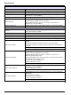
Standard Operations Table 15 Error register Bit Error Description 5 Hardware error Hardware error detected. 6 Internal communication error A communication failure within the device has been detected. 7 Humidity error Excessive humidity has been detected. 8 Temperature error Temperature within the device exceeds specified limit. 10 Sample warning Some action is required with the sample system. 11 Questionable calibration warning The last calibration was of questionable accuracy.
Standard Operations 5.12.3 Profibus/Modbus configuration example Table 17 and Table 18 show a Profibus/Modbus configuration example.
Standard Operations 5.13 Remote control The sc1000 controller supports remote control through dial-up connection (GSM modem) and LAN connection (service port) . The sc1000 controller is operated remotely with a web browser from a computer to configure the controller, download data logs and upload software updates. For detailed information on the LAN connection, refer to section 3.9 on page 44 For detailed information on the GSM connection, refer to section 3.10 on page 45. 5.13.
Standard Operations To add a fixed IP address to the computer: 1. In the Windows Start menu click Programs, Settings, Control Panel, Network Connections. 2. Right-click the Local Area Connection (LAN) option and select the Properties command. 3. In the LAN Connection dialog box select Internet Protocol (TCP/IP) and press the Properties button. 4. In the General tab select Use the following IP address radio box. 5. In the IP address box enter the computer IP address. 6. In the Subnet mask box enter 255.255.
Standard Operations To set computer settings (description for Windows XP): 1. Attach a modem to the computer and install the modem drivers. 2. In the Windows Start menu, select Programs, Accessories, Communications, New Connection Wizard to add a new dial-up connection. 3.
Standard Operations 5.13.4 Access the sc1000 controller through a web browser A web browser serves as the interface to administer the sc1000 controller remotely (GSM connection) or through LAN. The web browser access provides the functionality of the sc1000 controller software except adding/removing/changing devices and telegram configuration of the network modules. To access an sc1000 controller through a web browser: 1. On the sc1000 controller switch to the measured value display. 2.
Standard Operations 5.14 Log data The sc1000 controller provides a data log and an event log for each device/probe. The data log contains the measured data at selected intervals. The event log contains a large number of events that occur on the instruments, such as configuration changes, alarms and warnings, etc. The data log and the event log can be exported to the .csv, .txt and .zip file format. The logs can be downloaded on a storage card or with browser access on a hard disk drive of a computer. 5.
Standard Operations 5.14.3 Remove log files through browser access To remove log files through browser access: 1. Connect to a computer and open the browser. 2. Log on to the sc1000 controller. 3. Press the LOGGER button. 4. Press the ERASE LOG button. 5. A list of probes/devices is displayed. 6. Select one of the probes/devices. 7. Confirm the selection. 8. The log file is deleted. 9. Click the HOME button to return to the sc1000 home page.
Standard Operations 5.15 Formula editor for output and relay card Formulas can be used as additional signal source for output and relay cards (DIN rail and expansion cards). Each channel of the output or relay card can be used to run a formula. The result of a formula can be used the same way like real measured values. By using formulas, “virtual measurements” can be created (for example average values from measured values of multiple probes).
Standard Operations Common examples for formulas are “LOAD” or “DELTA-pH” (Table 22): • Load Basin1=concentration x flow • Delta-pH=(pH IN) – (pH OUT) Table 22 Formula settings—Example Function Description Name LOAD Location BASIN1 Unit kg/h Parameter Q Formula (AxB)/100 Add (Tag) A=Nitrate NO3 1125425 NITRATAX plus sc B=Volume m3/h Q Important Note: Formulas are not checked for validity. 5.15.
Standard Operations Table 23 Formula editor—Arithmetic operations Operation Formula Addition A+B Subtraction A-B Description Multiplication AxB Division A/B Takes value 1 when B=0: Error “ARGUMENT” is set. Power A^B Takes value |A|^B, no error is set, when A<0. Sign -A Parenthesis (...) Calculates everything in parenthesis, then applies operators outside.
Standard Operations A set of functions is available to set the error and warning status of output modules. Each of these functions requires a minimum of 2 (or 3) parameters and allows a maximum of 32 parameters. In calculations all functions take the value of first argument A as the function result, so the use of these functions does not affect the calculated value.
Section 6 Advanced Operations The following section describes all software settings for the sc1000 controller. The software settings from the Main Menu include: • SENSOR STATUS • SENSOR SETUP • SYSTEM SETUP • TEST/MAINT 6.1 Sensor status menu The sensor status menu lists errors and warnings of all connected probes/devices. If a probe is displayed in red, an error or a warning has been detected. SENSOR STATUS Select Device ERROR LIST Displays a list of errors currently present in the probe.
Advanced Operations 6.3 System setup menu The system setup menu contains the main configuration settings for the sc1000 controller. The system setup menu can include following items: • OUTPUT SETUP • CURRENT INPUTS • RELAY • NETWORK MODULES • GSM-MODULE • DEVICE MANAGEMENT • DISPLAY SETTINGS • BROWSER ACCESS • STORAGE CARD • SECURITY SETUP The availability of the menu items depends on the installed internal plug-in expansion cards or external DIN rail modules. 6.3.
Advanced Operations SYSTEM SETUP OUTPUT SETUP mA OUTPUT INT/EXT Select OUTPUT card 1,2,3 or 4 SELECT SOURCE Default value: No source Selects a probe or creates a formula which delivers the process value that is processed by the current output card. SET PARAMETER Default value: No Parameter Selects a parameter of the selected source. DATA VIEW Default value: INPUT VALUE Sets the displayed and logged measured value.
Advanced Operations SYSTEM SETUP OUTPUT SETUP mA OUTPUT INT/EXT PROPORTIONAL Default value: 0 Sets the proportional part of the PID controller (in minutes). The proportional part of the controller generates an output signal which is linearly dependent to the control deviation. This part responds directly to any changes at the input but starts to oscillate easily if set to high. The proportional part cannot completely compensate disturbances.
Advanced Operations Relation between input current and calculated concentration Figure 50 shows the output current depending on the process value, the set low value and the set high value with an output range of 0–20 mA. Figure 50 Output current with an output range of 0–20mA 1 Output current (OC) (y-axis) 5 Low value (LV) 2 OC=f(PV) 6 0 mA 3 Process value (PV) (x-axis) 7 20 mA 4 High value (HV) The output current (OC) is a function of the process value (PV).
Advanced Operations Figure 51 shows the output current depending on the process value, the set low value and the set high value with an output range of 4–20 mA.
Advanced Operations 6.3.2 Current inputs menu Note: The menus appear only if an input card is installed in the sc1000 controller. The current input card can be used as an analog input card to measure an input current in a range from 0–20 mA or 4–20 mA or it can be used as an digital input card. The current input menu content depends on its use: ANALOG CURRENT INPUT The current input card connects devices with a current input interface to the sc1000 controller.
Advanced Operations SYSTEM SETUP CURRENT INPUTS mA INPUT INT/EXT LOGIC Default value: DIRECT Sets the relation between input state and output level. The menu item is displayed if SET FUNCTION is set to DIGITAL. DIRECT If the input contact is closed the output level is LOW respectively if the input contact is open the output level is HIGH. REVERSE If the input contact is closed the output level is HIGH respectively if the input contact is open the output level is LOW.
Advanced Operations Relation between input current and calculated concentration Figure 52 shows the output value depending on the input current, the set low value and the set high value with an input range of 0–20 mA. Figure 52 Output value with an input range of 0–20 mA 1 Output value (concentration) (x-axis) 5 0 mA 2 OV=f(IC) 6 Low value (LV) 3 Input current (IC) (y-axis) 7 High value (HV) 4 20 mA The output value (OV) is a function of the input current (IC).
Advanced Operations Figure 53 shows the output value depending on the input current, the set low value and the set high value with an input range of 4–20 mA.
Advanced Operations 6.3.3 Relay menu Note: This menu appears only if a relay card is installed in the sc1000 controller. The relay menu content for a relay card depends on the selected working mode. There are several relay card working modes: ALARM Relay controls if a process value is between two limits. FEEDER CONTROL Relay indicates if a process value exceeds or falls below a set point. 2 POINT CONTROL Relay toggles if a process value reaches an upper or lower limit.
Advanced Operations SYSTEM SETUP RELAY RELAY INT/EXT FEEDER CONTROL Operates in response to the measured parameter. Can be set for phasing, set point, deadband, overfeed timer, and ON/OFF delay. 2 POINT CONTROL Operates in response to the measured parameter using two setpoints. WARNING Activated when the analyzer detects a probe warning. Indicates warning and error condition of selected probes. PWM Control Allows the relay to provide a pulse width modulated output. FREQ.
Advanced Operations Figure 54 shows the behavior of the relay in the alarm mode under different conditions.
Advanced Operations 6.3.3.3 Function set to FEEDER CONTROL working mode FEEDER CONTROL 90 SET TRANSFER Default value: DE-ENERGIZED Sets the status of the relay (ENERGIZED/DE-ENERGIZED) if error conditions are detected in the selected source or if the source is missing. PHASE Default value: HIGH Defines the relay status if the process value exceeds the set point. HIGH Turns the relay on when the process value exceeds the set point.
Advanced Operations Figure 55 and Figure 56 show the behavior of the relay in the Feeder Control function under different conditions.
Advanced Operations Figure 56 Relay behavior—Feeder Control mode (Phase low, OnMax Timer) 1 Deadband 5 ON delay 2 Set point 6 OFF delay 3 OnMax Timer 7 Source (y-axis) 4 Time (x-axis) Table 29 Color/line code for Figure 56 Selected source Relay contact (phase low) 92
Advanced Operations 6.3.3.4 Function set to 2 POINT CONTROL working mode 2 POINT CONTROL SET TRANSFER Default value: DE-ENERGIZED Sets the status of the relay (ENERGIZED/DE-ENERGIZED) if error conditions are detected in the selected source or if the source is missing. PHASE Default value: HIGH Sets the status of the relay. As soon as the process value enters the band between high and low alarm, the relay state is not changed.
Advanced Operations 2 POINT CONTROL Default value: 0 seconds (off) Indicates a period of time (in seconds) for the release of the OnMin TIMER and the OffMin TIMER. Relay turned on, OnMin TIMER activated: Displays the time left before the relay can be turned OFF again. Relay turned off, OffMax TIMER activated: Displays the time left before the relay can be turned ON again. MIN TIMER EXPIRE Figure 57-Figure 59 show the behavior of the relay in the 2 Point Control function under different conditions.
Advanced Operations Figure 58 Relay behavior—2 POINT Control mode (OnMin Timer, OnMax Timer) 1 High Alarm 5 OffMin Timer 2 Low Alarm 6 OnMin Timer 3 OnMin Timer 7 Source (y-axis) 4 Time (x-axis) Table 31 Color/line code for Figure 58 Selected Source Relay contact (phase high) 95
Advanced Operations Figure 59 Relay behavior—2 POINT Control mode (ON/OFF delay) 1 High Alarm 4 OFF delay (when phase is low) ON delay (when phase is high) 2 Low Alarm 5 Time (x-axis) 3 ON delay (when phase is low) OFF delay (when phase is high) 6 Source (y-axis) Table 32 Color/line code for Figure 59 Selected Source Relay contact (phase low) Relay contact (phase high) 96
Advanced Operations 6.3.3.5 Function set to WARNING working mode WARNING WARNING LIST Default value: Disabled Sets the monitoring of the internal warning bits of the selected source. ENABLED: Monitoring is active. DISABLED: Monitoring is not active. ERROR LIST Default value: Disabled Sets the monitoring of the internal error bits of the selected source. ENABLED: Monitoring is active. DISABLED: Monitoring is not active.
Advanced Operations Figure 60 shows the behavior of the relay in the Warning mode under different conditions.
Advanced Operations 6.3.3.6 Function set to PWM CONTROL/LINEAR working mode PWM CONTROL/LINEAR SET FUNCTION Default value: LINEAR The 2nd SET FUNCTION menu sets the PWM signal status LINEAR Signal is linearly dependent on the process value. PID CONTROL Signal works as a PID controller. SET TRANSFER Default value: 0 seconds Sets a substitute PWM ratio when some error conditions are detected in the selected source or if the source is missing.
Advanced Operations Figure 61 PWM Control/Linear mode—Maximum value 1 Process value (x-axis) 3 Low alarm 2 High alarm 4 Output ratio (y-axis) 100
Advanced Operations Figure 62 shows the behavior of the relay in the PWM Control/linear mode.
Advanced Operations 6.3.3.7 Function set to PWM CONTROL/PID CONTROL working mode PWM CONTROL/PID CONTROL SET FUNCTION Default value: LINEAR The 2nd SET FUNCTION menu sets the PWM signal status. LINEAR Signal is linearly dependent on the process value. PID CONTROL Signal works as a PID controller. SET TRANSFER Default value: 0% Sets a substitute PWM ratio when some error conditions are detected in the selected source or if the source is missing.
Advanced Operations PWM CONTROL/PID CONTROL INPUT VALUE Displays the process value read from the selected source after it has been processed by the internal formula parser (if prompted). With the PWM CONTROL/PID CONTROL the relay generates a PWM (Pulse-Width-Modulated) signal with an on/off ratio trying to control the process value. 6.3.3.8 Function set to FREQ. Control / Linear working mode FREQ. Control / Linear SET FUNCTION Default value: LINEAR There are two SET FUNCTION menus.
Advanced Operations Figure 63 shows the behavior of the relay in the FREQ. Control/Linear mode. Figure 63 Relay behavior—FREQ.
Advanced Operations 6.3.3.9 Function set to FREQ. Control/PID CONTROL mode FREQ. Control /PID CONTROL SET FUNCTION Default value: LINEAR There are two SET FUNCTION menus. First menu: Selects the basic function of the relay. Second menu: Defines whether the output frequency signal is depending linear to the process value or the output frequency signal is working as a PID controller. LINEAR Signal is linearly dependent on the process value. PID CONTROL Signal works as a PID controller.
Advanced Operations FREQ. Control /PID CONTROL INPUT VALUE Displays the process value read from the selected source after it has been processed by the internal formula parser (if prompted). 6.3.3.10 Function set to TIMER working mode TIMER SENSOR Default value: No source Select a probe or create a formula which delivers the process value that is to be processed by the relay card.
Advanced Operations Figure 64 shows the behavior of the relay in the Timer mode.
Advanced Operations 6.3.3.11 Function set to SYSTEM ERROR working mode SYSTEM ERROR WARNING LIST Default value: DISABLED ENABLED: Monitors the internal warning bits of every probe. DISABLED: Monitoring is disabled. ERROR LIST Default value: DISABLED ENABLED: Monitors the internal error bits of every probe. DISABLED: Monitoring is disabled. SENSOR MISSING Default value: DISABLED Monitors the connection of every connected probe. ENABLED: Monitoring is active. DISABLED: Monitoring is not active.
Advanced Operations 6.3.4 Network Modules (Profibus, Modbus) The sc1000 controller can be embedded as a slave into an existing fieldbus system. The Network Modules menu displays all the settings needed, the menu content depends on the communication gateway used, Profibus DP or Modbus. Note: This menu is displayed only if a network card is installed in the sc1000 controller. 6.3.4.1 Profibus SYSTEM SETUP NETWORK MODULES FIELDBUS TELEGRAM Builds an individual composition of data from different devices.
Advanced Operations SYSTEM SETUP NETWORK MODULES FIELDBUS TEST/MAINT Default value: DISABLED DISABLED: Normal operation mode ENABLED: Sets the TEST/MAINT bit (0x0040) of every status register of every configured slave to indicate the “Service” mode. VERSION Displays the current software version of the Profibus network adapter card. LOCATION Displays the current location.
Advanced Operations 6.3.4.2 Modbus SYSTEM SETUP NETWORK MODULES FIELDBUS TELEGRAM Sets up an Modbus slave which is based on individual composition of data from different devices. For details refer to section 5.12 on page 62. MODBUS MODBUS ADRESS Default value: 0 Sets the address (1 to 247) of the Modbus slave which was configured in the TELEGRAM menu. VIRTUAL SLAVES Default value: DISABLED Virtual slaves can be added.
Advanced Operations SYSTEM SETUP NETWORK MODULES FIELDBUS TEST/MAINT Default value: DISABLED This menu works independently from the simulation. DISABLED: Normal operation mode ENABLED: Sets the TEST/MAINT bit (0x0040) of every status register of every configured slave to indicate the “Service” mode. VERSION Displays the current software version of the Modbus network adapter card. LOCATION Displays the current location.
Advanced Operations 6.3.5 GSM module The GSM Module menu contains all settings which are needed for remote communication (dial-up) between the sc1000 controller and a computer. For more detailed information refer to section 3.10 on page 45. Note: This menu is displayed only if a GSM modem is installed in the sc1000 controller SYSTEM SETUP GSM MODULE PROVIDER Displays the current mobile network.
Advanced Operations SYSTEM SETUP GSM MODULE INHIBIT SMS REPETITIONS Default value: “OFF” OFF: SMS messages are sent repeatedly. ON: SMS messages are not sent repeatedly. CONFIGURE The display module observes the states of the configured devices included in this list. ADD Adds a device to the CONFIGURE list Displays all installed devices including the sc1000. Devices that are already in the CONFIGURE list are grayed-out. ERASE Removes a device from the CONFIGURE list.
Advanced Operations 6.3.6 Device management The Device Management menu contains all settings for administering devices which are connected to the sc1000 controller. For information on adding new devices/probes refer to section 5.11 on page 61. SYSTEM SETUP DEVICE MANAGEMENT DEVICE LIST Lists all probes and modules which are installed and registered in the sc1000 controller. SCANNING FOR NEW DEVICES Scans for new probes and modules.
Advanced Operations 6.3.8 Browser access The Browser access menu contains communication settings for a LAN connection between the sc1000 controller and a computer. For more detailed information refer to section 5.13.4 on page 70. SYSTEM SETUP BROWSER ACCESS LOGIN PASSWORD Login password for remote (GSM)/LAN-access IP ADDRESS Default value: 192.168.154.30 Enter an IP address to identify the sc1000 controller on the network. NETMASK Default value: 255.255.255.
Advanced Operations 6.3.10 Security setup The Security Setup menu allows to set a passcode to protect the sc1000 controller from unauthorized access. For more detailed information refer to section 5.9 on page 60. SYSTEM SETUP SECURITY SETUP MAINTANENCE Enter the MAINTANENCE passcode. OFF: Clear the current passcode in the edit screen and confirm. SYSTEM Enter the SYSTEM passcode. OFF: Clear the current passcode in the edit screen and confirm. 6.
Advanced Operations TEST/MAINT DISPLAY INFO SOFTWARE VERSION Displays the software version of the display module SERIAL NUMBER Displays the serial number of the display module 6.4.1 Bus status The Bus Status menu informs the user about communication problems which might restrict data availability and degrade the overall sc1000 controller operation. More detailed information can be obtained from the Diagnostic file (refer to section 6.3.9 on page 116).
Section 7 Maintenance DANGER Electrocution and fire hazard. Only qualified personnel should conduct the installation tasks described in this section of the manual. 7.1 General maintenance • Regularly check the probe module and the display module for mechanical damage. • Regularly check all connections for leaks and corrosion. • Regularly check all cables for mechanical damage. • Clean the probe module and the display module with a soft, damp cloth. Use mild detergent, if necessary. 7.
Maintenance Figure 67 Fuse replacement (AC version) 1 Fuse (2), F1 and F2: M 3.5A medium slow-blow 3 Remove fuse from holder as shown. 2 Fuse (2), F3 and F4: T 8A; 100–240 VDC, slow-blow 4 Fuse holder 1 Fuse, T 6.3A, slow-blow 2 Remove fuse from holder as shown.
Section 8 Troubleshooting 8.1 General problems and GSM module errors Table 39 General Problems Problem Cause/Solution Incorrect display reaction when the display is touched Calibrate touch screen with finger or stylus. If this is not possible: Start factory calibration through web access. No trend line available. Configure the logger in the appropriate probe. Communication problems Check the probe plug, check probe cable damage, check network plug and cable at sc1000 networks.
Troubleshooting 8.2 GSM Module errors Table 40 GSM Module errors Problem Solution sc1000 does not answer an incoming call. Select SYSTEM SETUP, GSM MODULE, EXTERNAL DIAL-UP and select the “Allow” option. Service login is not possible via GSM connection. Select SYSTEM SETUP, GSM MODULE, EXTERNAL DIAL-UP and select the “Allow” option. Login is not possible via GSM connection. Select SYSTEM SETUP, BROWSER ACCESS and set a LOGIN PASSWORD. GSM module does not get network access.
Troubleshooting 8.3.2 Message format Table 42 and Table 43 show the message window formats: Table 42 Message window format Date Warning/Error text Device name Local Time Warning/Error ID number Serial number device Event counter Table 43 Message window example 2007-12-18 Communication Error LDO 18:07:32 [405410120] (1) 8.3.
Troubleshooting 8.4 SMS service Provided the display module is equipped with a GSM modem and a SIM card, the sc1000 controller can send SMS to up to five destinations if an error or a warning in an attached device occurs (refer to section 8.3 on page 122). The following messages are sent via SMS: • Not confirmed messages which are stored in the message list. • New messages which are displayed in the message window. Important Note: To stop sending SMS repeatedly, confirm the message window.
Troubleshooting Table 47 SMS format description Manufacturer ID Manufacturer ID Instrument ID Instrument ID Table 48 SMS example E32 HACH-LANGE Trailer 01726428973 000001138172 RELAY INT Reservoir 1 000000002283 COMMUNICATION ER 061128 1332 001 49155 125
Troubleshooting 8.5 Test the expansion cards in the Maintenance menu 8.5.1 Test the output card In the TEST/MAINT menu, every output current can be set to certain values for testing reasons. If necessary, each output can be adjusted as well. Additionally, the current state of the outputs can be requested. The output current can be set to certain values and then be adjusted with an offset and a factor. To set these two parameters: 1. Set the SET OFFSET value to “0” and the SET FACTOR value to “1”. 2.
Troubleshooting 8.5.2 Test the input card In the TEST/MAINT menu, every input current channel can be checked. If necessary, each input can be adjusted as well. The input current can be checked by setting a defined current to the according channel and then comparing it with the displayed value. If necessary, the displayed value can be adjusted with an offset and a factor. To set these parameters: 1. Set the SET OFFSET value to “0” and the SET FACTOR value to “1”. 2.
Troubleshooting 8.5.3 Test the relay card In the TEST/MAINT menu, the relay function can be checked. The relay function can be tested by manually switching the single relays on or off in the FUNCTION TEST menu. Additionally, the current state of the relays can be requested in the RELAY STATUS menu. TEST/MAINT OUTPUT SETUP RELAY INT/EXT FUNCTION TEST RELAY 1-4 Sets the relay to on or off.
Section 9 Replacement Parts and Accessories 9.1 Expansion cards Description QTY Item No. Internal input card, analog/digital with 4x (0–20/4–20 mA) or 4 x digital IN 1 YAB018 Internal output card, analog with 4x (0–20/4–20 mA) OUTPUT 1 YAB019 Internal Profibus DP card 1 YAB020 Internal Modbus card (RS485) 1 YAB021 Internal relay card with 4 relays, max. 240 V 1 YAB022 Internal Modbus card (RS232) 1 YAB047 Description QTY Item No.
Replacement Parts and Accessories 9.4 Accessories (continued) Description QTY Item No. External antenna 1 LZX990 Extension cable for external antenna 1 LZX955 9.5 Replacement parts Refer to Exploded view drawings, Figure 69 on page 132–Figure 72 on page 135 Item 130 Description Item No.
Replacement Parts and Accessories 9.5 Replacement parts (continued) Refer to Exploded view drawings, Figure 69 on page 132–Figure 72 on page 135 Item Description Item No.
Replacement Parts and Accessories 9.6 Exploded view drawings The assembly drawings in this section are provided to identify replaceable components for service only. DANGER Electrocution hazard. This product contains high voltage sufficient to cause electrocution and fire related hazard. Do not attempt any service activity without a certified electrical technician.
Replacement Parts and Accessories Figure 70 Probe module connections 133
Replacement Parts and Accessories Figure 71 Probe module circuit cards 134
Replacement Parts and Accessories Figure 72 Display module 135
Replacement Parts and Accessories 136
Section 10 Contact Information HACH Company World Headquarters P.O. Box 389 Loveland, Colorado 80539-0389 U.S.A. Tel (800) 227-HACH (800) -227-4224 (U.S.A. only) Fax (970) 669-2932 orders@hach.com www.hach.com Repair Service in the United States: HACH Company Ames Service 100 Dayton Avenue Ames, Iowa 50010 Tel (800) 227-4224 (U.S.A. only) Fax (515) 232-3835 Repair Service in Canada: Hach Sales & Service Canada Ltd.
Contact Information 138
Section 11 Certification The manufacturer certifies this instrument was tested thoroughly, inspected and found to meet its published specifications when it was shipped from the factory. Canadian Interference-causing Equipment Regulation, IECS-003, Class A Supporting test records by ETS Product Service AG, Storkower Str. 38c, 15526 Reichenwalde and certified compliance by the manufacturer. This Class A digital apparatus meets all requirements of the Canadian InterferenceCausing Equipment Regulations.
Certification 140
Appendix A DIN Rail Expansion Modules A.1 Mount the DIN rail 1. Make sure that the wall is dry, flat, structurally suitable, and not electrically conductive. 2. Align the DIN rail so that it is level. 3. Bolt the rail to the wall. 4. Connect a protective earth ground from the DIN rail. A.2 Attach an expansion module CAUTION If AC power is to be connected to the relay module(s), the relay module(s) must not be connected to, nor installed in the same enclosure as modules connected to low voltage devices (e.
Figure 74 Attaching multiple expansion modules A.3 Attach the base module The base module provides a connection for a display module and contains a connection and the terminating resistor for the sc1000 network. The LED on the front indicates the status of the network communication. The base module is required for any additional modules. Prior to installing the base module, make sure the DIN rail is mounted correctly and that all safety requirements are met. 1.
Figure 76 External base module Table 49 Base Module Terminal Assignments Terminal Terminal assignment Description 1 + 24 VDC Power Supply (+) 2 Not used — 3 0V Power Supply (–) 4 PE (Protective Earth) Ground 24 V 5 + For sc1000 network expansion, coming 6 – For sc1000 network expansion, coming 7 Not used — 8 PE (Protective Earth) Ground network connection 9–12 Not used — 13 + For sc1000 network expansion, going 14 – For sc1000 network expansion, going 15 Not used — 16
A.4 Attach the external relay module The external relay card provides 4 relays, each with one change-over contact. The relays can switch maximum 250 VAC, 5A (UL, SPDT-CO, change-over). They can be programmed for limits, status, timers, and special functions. 1. Remove power and disconnect all cable connections to the module. 2. Place the external relay module on the DIN rail to the right of the base module and slide firmly against the base module (or other connected modules). 3.
A.5 Attach the external output module The output module provides two outputs, 0–20 mA/4–20 mA, 500 Ohm. 1. Remove power and disconnect all cable connections to the module. 2. Place the External Output Module on the DIN rail to the right of the base module and slide firmly against the base module (or other connected modules). 3. Make the appropriate connections as shown in Figure 78 and Table 51. 4. Connect cables to the module and reconnect power from the instrument.
A.6 Attach the external input module Instruments with (0–20 mA/4–20 mA) outputs can be connected to this module. The signals can be scaled as required and be given names and units. Instruments that do not have network options can be connected to the network system using a sc1000 with Modbus or Profibus. In addition, this module can be used to monitor floating digital switches (external relay contacts as inputs). The module cannot be used to provide 24V power to a 2-wire (loop-powered) device.
A.7 Dismantle the DIN rail 1. Delete the module(s) in the sc1000 controller. 2. Remove power and disconnect all cable connections to the module(s). 3. Separate the module(s) on the DIN rail by sliding it to one side. 4. Use a suitable tool (i.e., screw driver) to pull down on the rear of the module. 5. Tip the bottom of the module away from the DIN rail and lift to remove.
148