Table of Contents DECLARATION OF CONFORMITY . . . . . . . . . . . . . . . . . . . . . . . . . . . . . . . . . . . . . . . . . . . . . . . . . . . . . . . . . . . . . . . . . . . . . . . . . . . . . . . . . . . . . . . . . . . . . . . . . . . . . 2 SAFETY INFORMATION . . . . . . . . . . . . . . . . . . . . . . . . . . . . . . . . . . . . . . . . . . . . . . . . . . . . . . . . . . . . . . . . . . . . . . . . . . . . . . . . . . . . . . . . . . . . . . . . . . . . . . . . . . . . . .3 SPECIFICATIONS . . . . .
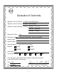
Declaration of Conformity Application of Council Directive: 73/23/EEC (low voltage directive) Application of Council Directive: 89/336/EEC (EMC Directive) Standard(s) to which Conformity is Declared: EN55103 -1 (Emissions) EN55103 -2 (Immunity) EN60065 Manufacturer’s Name: (Safety) Hafler Manufacturer’s Address: 546 South Rockford Drive, Tempe, Arizona 85281 Importer’s Name: Importer’s Address: Type of Equipment: 2-channel Audio Power Amplifier Model No.
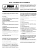
NOTICE - IMPORTANT SAFETY INFORMATION CAUTION RISK OF ELECTRIC SHOCK DO NOT OPEN ! WARNING: TO PREVENT FIRE OR SHOCK HAZARD DO NOT EXPOSE THIS EQUIPMENT TO RAIN OR MOISTURE. 1. READ INSTRUCTIONS All the safety and operating instructions of your Hafler equipment should be read before power is applied to the equipment. 2. RETAIN OWNER'S MANUAL These safety and operating instructions should be retained for future reference. 3.
ADVERTENCIA – INFORMACION DE SEGURIDAD IMPORTANTE PELIGRO RIESGO DE DESCARGA ´ ´ ELECTRICA NO ABRIR. El símbolo de flecha relámpago dentro de un triángulo equilátero, es para alertar al usario de la presencia de “voltajes peligrosos” no aislados en el interior del aparato, los cuales pueden ser de suficiente magnitud para constituir un riesgo de choque eléctrico a las personas.
ACHTUNG – WICHTIGE SICHERHEITS – INFORMATIONEN ACHTUNG GEFAHR EINES ELEKTRISCHEN SCHLAGS ¨ NICHT OFFNEN ! Der Blitz mit dem Pfeil, in einem gleihschenkligen Dreieck, soll den benutzer vor unisolierter “gefährlicher Spannung” innerhalb des Gerätes warnen. Das Ausrufezeichen, in einem gleichschenkligen Dreieck, soll den Benutzer darauf aufmerksam machen, dab dem Gerät wichtige Operations - und Service - Informationen beigefügt sind.
ATTENTION: INFORMATIONS IMPORTANTES DE SÉCURITÉ ATTENTION RISQUE DE CHOC ´ ELECTRIQUE NE PAS OUVRIR ! AVERTISSEMENT: ´ Afin de prevenir les risques de feu ou de choc, ne pas ´ la pluie ou ´a l'humidité exposer cet appareil a 1.
NOTARE – IMPORTANTI INFORMAZIONI SULLA SICUREZZA ATTENZIONE ATTENZIONE: RISCHIO DE SCARICHE ELETTRICHE NON APRIRE Il simbolo del fulmine in un triangolo equilatero vuole avvertire della presenza di tensioni elevate non isolate e di valore sufficiente per costituire rischio di shock elettrico alle persone. ! Il punto esclamativo contentuto in un triangolo equilatero vuole avvertire l'utente della presenza di parti di servizio e di manutenzione che sono dettagliate nel manuale di istruzioni.
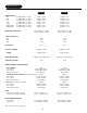
Specifications All measurements taken at Normal Operating Conditions (i.e. 1/8th rated output power) unless noted otherwise. GX2300 POWER RATING: 8Ω 20-20kHz 4Ω 20-20kHz 2Ω 20-20kHz 70V 20-20kHz 100V 20-20kHz Bridged 8Ω 20-20kHz Bridged 4Ω 20-20kHz @ @ @ @ @ @ @ 0.1% 0.2% 0.3% 0.2% 0.2% 0.2% 0.3% THD THD THD THD THD THD THD FREQUENCY RESPONSE: 300W 300W 300W 600W 600W 600W 600W x x x x x x x 2 2 2 1 1 1 1 CH CH CH CH CH CH CH 10Hz-20kHz +/–0.1dB 0.
Specifications (cont) 70V 100v 4Ω 8Ω 2Ω -18-15 -12 -21 -9 -24 -6 -27 -3 -32 -38 Channel A CH A OFF signal Load 70V 100v 4Ω 8Ω 2Ω Power 2300 protect thermal clip Channel b CH B -18-15 -12 -21 -9 -24 -6 -27 -3 -32 -38 OFF DIMENSIONS: WEIGHT: 0dB Stereo Mono 70V 100V 0dB (2U) 3.5H" x 19"W x 18.5"D (rack handles add 1.25"D) (2U) 3.5H" x 19"W x 18.5"D (rack handles add 1.25"D) 32lbs. (14.51 kg) 32lbs. (14.
WHAT ELSE DISTINGUISHES THESE AMPLIFIERS? Constant power into varying impedance. It takes twice as much current to develop a given wattage into 2Ω as it does into 8Ω—but only half the voltage. Many amplifiers quote a high output current at 2Ω but have an unpublished operating time measured in a handful of seconds—before thermal shutdown (hopefully) precludes thermal meltdown. Our solution for this is selectable rail voltages for optimizing the amplifier to the load.
Design Features 70V 100v 4Ω 8Ω 2Ω -18-15 -12 -21 -9 -24 -6 -27 -3 -32 -38 Channel A CH A OFF signal Load Power 70V 100v 4Ω 8Ω 2Ω 2300 protect -18-15 -12 -21 -9 -24 -6 -27 -3 -32 -38 thermal clip Channel b CH B 0dB Stereo Mono 70V 100V OFF 1 9 2 4 3 7 0dB 8 12 180˚– HP – Crossover LP – CH A IN BIAMP STEREO CD EQ Full – +0 2 +10 dB Freq 500Hz – 800Hz – CH B IN (Mono) 0˚– ON Phase 6 0”6”12”18”24”30”- — + Delay must choose one only 600W For 70V, 100V, or Mono • Use CH
Installation The GX2300/2600 is a standard 2U (2 rack height) 19" rack-mount unit, with both front and rear rack mounting ears. In portable systems, the amplifier must be supported at both the front and rear. ! COOLING The GX2300/2600 uses forced-air cooling (fan cooling) to remove the heat produced during normal operation. Free air flow at the mounting location is a critical factor in accomplishing long-term reliable operation of the amplifier.
AUDIO GROUND CHASSIS/FLOAT SWITCH In general, the Audio Ground of each amplifier should be connected to AC mains earth ground AT ONE POINT ONLYeither through the Chassis (by selecting the "Chassis" position) OR through the input cable (with the switch in the "Float" position, and pin 1 of the XLR or the sleeve of the 1/4" connected to the ground of the signal source unit.) The Chassis/Float switch can be used as a means to troubleshoot ground loop problems, or to verify wiring.
Operation The amplifier will operate with either a balanced or unbalanced signal source. INPUT The input jacks used on the GX2300/2600 are dual function connectors which accept 1/4" TRS (Tip Ring Sleeve) or male XLR plugs. The amplifier will operate with either a balanced or unbalanced signal, from earth ground or floated source equipment. To determine if your equipment is earth grounded or floated, consult the owner’s manual or test with an ohmmeter.
GROUNDED, UNBALANCED SOURCE XLR, 1/4" Mono Amplifier 2 COAX OR TWISTED PAIR 3 Shield Audio Ground 1 Float 1/4" Mono: sleeve shorts — input to Audio Ground; XLR: short pins 1 & 3 together FLOATED SOURCE EQUIPMENT Source units with a 2-pin mains power cord have no means to connect the audio output ground to earth ground, so usually the audio output ground is floated from earth ground.
DELAY (One of these switches must be selected. If all the switches are OFF, there will be no output signal.) The delay feature provides five sections of 2nd-order all-pass delay filters of 450µsec +/-10µsec each. Unlike the more commonly used 1st-order all-pass, the 2nd-order filters achieve a constant delay time over the usable frequency range of 1Hz to 1kHz. At frequencies higher than 1kHZ, the gain remains flat, while the delay time gradually decreases to zero.
LEVEL CONTROLS The gain for each channel can be controlled individually using the front panel level control. The controls have 32 detented positions that are calibrated in dB. The maximum gain position is marked as the "0 dB" position, and the lower gain positions indicate the amount of attenuation relative to the maximum gain position in dB. Minimum gain position is marked as “Off” and represents over 100dB of attenuation relative to the maximum gain position.
LOAD SWITCH The Load Switch - located on the front panel - allows the amplifier power supply to be matched to the speaker load for more efficient, cooler running operation.This unique feature of the GX2300/2600 allows each channel to be configured for 2Ω, 4Ω, 8Ω, or 70V, 100V mono operation. (also 70V Dual Mono-GX2600 only). The power output and thermal performance of the amplifier remains consistent with all the possible combinations of the loads listed.
Wiring Diagrams STEREO MODE (GX2300/GX2600) - 1. Connect signal from source to both CH A and CH B inputs. 2. Move Stereo/Biamp switch to Stereo input mode. 3. Move Stereo/Mono switch to Stereo mode. 4. Select desired speaker load (8Ω/4Ω/2Ω) for each channel – CH A & CH B loads do not need to match. 5. Connect appropriate speaker load 8Ω/4Ω/2Ω to 5-way binding posts. 6. Adjust CH A & CH B level controls independently. BIAMP MODE (GX2300/GX2600) - 1. 2. 3. 4. Connect signal from source to CH B input.
BRIDGE MONO MODE (GX2300/GX2600) 70V 100v 4Ω 8Ω 2Ω -18-15 -12 -21 -9 -24 -6 -27 -3 -32 -38 Channel A CH A OFF signal Load Power 70V 100v 4Ω 8Ω 2Ω 2300 protect -18-15 -12 -21 -9 -24 -6 -27 -3 -32 -38 thermal clip Channel b CH B 0dB Stereo Mono 70V 100V OFF HP – LP – Full – 2 180˚– Crossover CD EQ +0 Freq BIAMP STEREO HP – LP – Full – +0 2 Phase 500Hz – Freq 800Hz – CH B IN (Mono) 300 W Stereo, 2Ω– 8Ω 600W Mono, 70V,100V Attention: Utiliser un fusible de rechange de même type.
100V MONO MODE (GX2300/GX2600) 1. Connect signal from source to CH B input. 2. Stereo/Biamp switch not active (Stereo/Mono switch overrides this switch when in mono/70V/100V mode). 3. Move Stereo/Mono switch to 100V mode. 4. Select 100V load, both channels. 5. Connect parallel array of 100V transformer-equipped speakers across the red terminals of the 5-way binding posts. (1200W – GX2600, 600W – GX2300) 6. CH B input sensitivity controls 100V mono output level. Amplifier will clip at 100Vrms level.
Service Policy and Limited Warranty Hafler offers a limited warranty on Hafler products on the following terms: • Length of Warranty 5 years on GX2300 & GX2600 • What is Covered This warranty applies only to products sold to the original owner (non-transferable). This only applies to units sold in the Continental United States. You are required to have a copy of the receipt stating the customer's name, dealer name, product purchased and date of purchase.
C147 DANGER - HIGH VOLTAGE X4 C7 R9 C4 C5 C9 C6 S1 X6 J1 R343 C12 J15 R33 R34 C21 R22 C18 R3 C23 K K C170 R4 C15 R26 CR49 R23 J5 U2 R24 J18 R20 C1 Z1 R316 R284 R10 J17 R2 R7 R8 J16 R12 R11 J19 C14 C13 J3 Q1 C16 C37 C17 R28 A A R32 R38 R39 R40 C33 C32 R41 R48 R49 C35 R50 U3 C34 Q8 R52 R51 CR64 A HS2 R47 A C24 C38 CR59 Q10 T1 C25 Q7 HIGH VOLTAGE C19 J14 R46 K CR65 CR2 C20 R30 R27 CR67 K K R17 R42 R15 Q6 K A A R
PC BOARD LAYOUTS EMI FILTER HAFLER PC-2460-E DANGER - HIGH VOLTAGE J2 J4 J3 C2 L3 KS4R J9 J6 BLACK BLACK J13 L1 C3 120V 120V C6 J5 J7 ORG ORG J14 J10 C7 230V 230V C5 L2 J8 J15 J11 WHT J1 J16 C1 C4 J12 WHT R1 R2 CROSSOVER CD EQ – 24 – R3 R4
PC BOARD LAYOUTS TIME DELAY/PHASE INVERTER – 25 –
Schematic Diagrams BRIDGE RECTIFIER – 26 –
PC-2460-e.
Schematic Diagrams CROSSOVER CD EQ – 28 –
TIME DELAY/PHASE INVERTER – 29 –
AMPLIFIER – 30 –
C600_maualB.
PROTECTION – 32 –
C600_maualB.
HIGH VOLTAGE CONTROL G – 34 –
GX 2300 – 35 –
HOUSEKEEPING CONTROL – 36 –
C600_maualB.
INPUT – 38 –
C600_maualB.
POWER – 40 –
C600_maualB.
A DIVISION OF ROCKFORD CORPORATION 546 SOUTH ROCKFORD DRIVE TEMPE, ARIZONA 85281 U.S.A. ® IN U.S.A.