Hafler Iris Preamplifier
It is a good habit to turn down BOTH remote and main panel volume controls upon system shut-down. This will avoid possible sudden and unexpected changes in volume when system is re-activated. TABLE OF CONTENTS Introduction ................................................................. Page 1 installation .................................................................. Page 2 Operation .................................................................... Page 5 IRIS Block Diagram .................
INSTALLATION The gloss black insert on the face-plate of your new Hafler Equipment has been packaged with a removable protective coating. Please peel off this protective coating following installation. When cleaning the face-plate, we advise a soft cotton cloth with a non-abrasive cleaner that is safe for lexan and painted surfaces. DO NOT use paper towels or any coarse material to clean the face-plate as these materials may scratch the insert. IRIS is shipped with styled end caps on its front panel.
Power Connections IRIS is internally connectable for virtually all AC line-power systems. Units not marked otherwise, on the rear panel, are connected for 120 Vofts, 50-60 Hz. Two SWITCHED outlets and one UNSWITCHED outlet (U.S. 120 Volt standards) are provided on the rear panel. The UNSWITCHED outlet is provided for powering certain mechanical equipment, if so recommended by its manufacturer.
The usual ground thumbscrew is provided for turntable-frame grounding via the extra ground wire provided on most turntables. High Level Inputs (Oval Key selected) IRIS has seven pairs of main HIGH LEVEL inputs, selected by the seven (oval) KEYS to the right of the phono KEY. All of these inputs proceed at unity gain to the attenuator/line-amplifier system, which has a maximum gain of 20dB. All of these basically identical inputs are selectable by the input KEY switches.
OPERATION CAUTION: The EPL switch and the tape MONITOR switches, explained later, are often the cause of an apparently “dead” system, when they have accidentally been left engaged. Always check them first if a system is found “dead” on turn-on. For now, make sure that all six of the group of round-button switches are in theirOUT position.
The actual audio attenuation elements are passive opticallycontrolled resistors, arranged in a special CYBER-OPTIC control circuit (patent applications in progress) which allows a combination of very low distortion and stereo tracking accuracy (typically 0.1dB) not previously possible in a passive, continuous control system. The BALANCE control produces approximately 13dB maximum cut in one channel, while boosting the other channel by 3dB-to maintain constant music power during control panning.
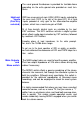
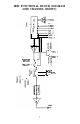
IRIS FUNCTIONAL BLOCK DIAGRAM (ONE CHANNEL SHOWN) bREC MON I TOR SWITCH 1 MON I TOR 2 SWITCH 0 e A 7 0 CUT IN EPL MAIN OUT 7 2
Recording System Any recording requires that you activate either the RECORD 1 jacks, the RECORD 2 jacks (or both) using the RECORD 1 or RECORD 2 switches on the panel. As seen in the signal flow diagram, this makes any input selectable by the KEYS available to these outputs. EXAMPLE: KEY-selecting TUNERwith RECORD 1 depressed will send both TUNER channels out the RECORD 1 jacks to the INPUTS of the tape deck.
Tape Monitoring Switches The tape MONITOR switches at first appear to allow only a redundant selection of what you hear from your deck(s) when you use the TAPE KEY(s). The important difference is that MONITOR switches actually BREAK the audio path inside the preamplifier, allowing you to listen to the deck’s OUTPUT while its INPUT is being fed from any source selectable by the KEYS. This feature is necessary for selectable by the KEYS.
USING THE IRIS REMOTE SYSTEM Infrared Remote Integrated System INTRODUCTION The IRIS preamplifier achieves its infrared (IR) remote capability by the addition of the IRIS remote RECEIVER board, which plugs into a keyed male connector at the top of the preamplifier’s Command/Memory/Display (CMD) board, containing the frontpanel key switches and legend LED's. IRIS employs a "carrier" of bright IR IR pulses modulated in frequency (25/35 kHz) by a 32-bit Pulse-Code-Modulation (PCM) signal.
Note: The touching of BOTH knobs simultaneously will sometimes inhibit operation of the touch-sensing system. The knobtouch system overrides any KEY-type command-so that KEY commands will not transmit, if you are accidentally touching either knob. The transmission of analog control positions to the preamplifier works much like the process used in digital recording and playback.
Note: Which V/B knob-set is in command is unaffected by ANY KEYS-remote or preamplifier. It depends ONLY in where the LAST V/B command came from (including the effects of preamplifier power-up discussed earlier). CAUTION: Since the IRIS remote is fun for many adults, it is likely that small children will also find it so. After a system turn-on, the REMOTE knobs may not be set where you left them at last listening.
The rear of the IRIS receiver card has a recessed, keyed male connector which carries needed digital signals for allowing the IRIS system to be connected to coming Hafler IRIS-compatible accessories, in a manner similar to which dispersed computer terminals can share the same data lines without confusion. The TUNER legend commands already on the remote will automatically route to the soon coming IRIS-compatible TUNER, after you have selected TUNER, if it is powered. Similar logic exists on the CD selection.
1) Remove the 4 screws on the bottom cover of the transmitter, and pull the cover off. 2) The battery polarities are clearly marked in the plastic holder, visible when the batteries are removed. Carefully observing these polarity markings, replace all 4 batteries. 3) Check IMMEDIATELY for normal transmitter operation by observing the RED transmitter indicator. It should now flash brightly. 4) Replace the bottom cover, making sure to orient it for the screw pattern, and replace the 4 screws.
Even if you are experimenting, you must replace the cover before re-plugging in the unit to AC-not only for safety reasons, but to shield hum and interference which can totally invalidate any attempts at sonic evaluation.
IRIS SPECIFICATIONS Phono Section: Output (Measurements at REC OUT) Frequency Response: 20Hz-20kHz, Maximum Voltage: 5 Volts RMS, 20Hz-20kHz Totul Harmonic Distortion & Noise Sensitivity: ±0.1 dB 20Hz-20kHz Moving Magnet: .002% Moving Coil: .009% (For 0.5 volts RMS @ 1 kHz Moving Magnet: 6.0 mV RMS Moving Coil: 600 p V RMS Signal to Noise Ratio: (A-weighted, relative to 0.5 V RMS) Moving Magnet: -87dB Moving Coil: -8OdB Maximum Input Signal: (@1kHz) Moving Magnet: 65 mV RMS Moving Coil: 6.
.005%, 20Hz-20kHz Total Harmonic Distortion & Noise: Sensitivity: (For 0.5 V RMS Output): 75 mV RMS Signal to Noise Input @ 2 volts RMS -97dB (A-weighted, relative to 2.
FACTORY SERVICE AND LIMITED WARRANTY If you encounter anydifficultyor have anyquestionsconcerning your IRIS preamplifier, please call our Customer Service Department weekdays, 8 am to 3:30 pm Mountain Standard time, at 602-967-3565. Before returning any unit to the factory for service, please call us. All units being returned (regardless of warranty status) must receive a Return Authorization (RA) Number.