P1500 / P3000 Installation & Operation ® ® a v o n s n a tr MAD IN T E HE USA PROFESSIONAL POWER AMPL AMPLIFIER
Declaration of Conformity Application of Council Directive: 73 / 23 / EEC (Low Voltage Directive) 89 / 336 / EEC (EMC Directive) Standard(s) to which Conformity is Declared: EN55103-1 EN55103-2 EN60065 Manufacturer’s Name: Hafler Manufacturer’s Address: 546 South Rockford Drive, Tempe, Arizona 85281 Importer’s Name: Importer’s Address: Type of Equipment: 2-channel Audio Power Amplifier/Speaker Model No.
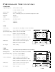
PERFORMANCE SPECIFICATIONS P1500/P3000 Frequency Response: 20Hz to 20kHz, ±0.1dB 0.15Hz to 300kHz, +0/–3dB Signal-to-Noise: >100dB “A” Weighted Distortion: <0.2% 20-20kHz, typically .01% at 1kHz @ rated power into 8Ω Slew Rate: 100 V/µs CMRR: 75dB at 1kHz Input Impedance: 47k ohms per phase Gain: +14dB min. +29dB max. P1500 Power Rating: 75 wpc @8 Ω, 85 wpc @ 4Ω, 170 Watts mono @ 8Ω Damping Factor: 350 (to 1kHz); 150 (to 10kHz); 18 (to 100kHz) 16.00 Input Sensitivity Range: 870mV - 4.
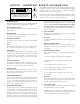
NOTICE - IMPORTANT SAFETY INFORMATION CAUTION RISK OF ELECTRIC SHOCK DO NOT OPEN The lightning flash with arrowhead symbol within an equilateral triangle is intended to alert the user to the presence of uninsulated "dangerous voltage" within the product's enclosure, that may be of sufficient magnitude to constitute a risk of electric shock to persons. ! WARNING: TO PREVENT FIRE OR SHOCK HAZARD, DO NOT EXPOSE THIS EQUIPMENT TO RAIN OR MOISTURE. ! 1.
ESPAÑOL ADVERTENCIA – INFORMACION DE SEGURIDAD IMPORTANTE PELIGRO RIESGO DE DESCARGA ELÉCTRICA NO ABRÍR. El símbolo de flecha relámpago dentro de un triángulo equilátero, es para alertar al usario de la presencia de “voltajes peligrosos” no aislados en el interior del aparato, los cuales pueden ser de suficiente magnitud para constituir un riesgo de choque eléctrico a las personas.
FRANÇAIS ATTENTION: INFORMATIONS IMPORTANTES DE SÉCURITÉ AT T E N T I O N RISQUE DE CHOC ÉLECTRIQUE NE PAS OUVRIR ! AVERTISSEMENT: Afin de prévenir les risques de feu ou de choc, ne pas exposer cet appareil à la pluie ou à l'humidité. La lumière clignotante du symbole de la flêche à l'intérieur d'un triangle équilatéral, à pour objet d'alerter l'utilisateur de la présence “d'un voltage dangereux” non-isolé à l'intérieur du produit, qui pourrait être de magnitude suffisante au risque d'éléctrocution.
DEUTSCH ACHTUNG – WICHTIGE SICHERHEITS – INFORMATIONEN ACHTUNG GEFAHR EINES ELEKTRISCHEN SCHLAGS NICHT ÖFFNEN ! WARNUNG: Um die gefahr eines elektroschocks oder feuer zu vermeiden, setzen sie das gerät keinem regen oder extremer feuchtigkeitaus. Der Blitz mit dem Pfeil, in einem gleihschenkligen Dreieck, soll den benutzer vor unisolierter “gefährlicher Spannung” innerhalb des Gerätes warnen.
ITALIANO NOTARE – IMPORTANTI INFORMAZIONI SULLA SICUREZZA AT T E N Z I O N E RISCHIO DI SCARICHE ELETTRICHE NON APRIRE ! ATTENZIONE: Per prevenire incendio scariche elettriche, non esporre questo apparato a pioggia o umiditá. Il simbolo del fulmine in un triangolo equilatero vuole avvertire della presenza di tensioni elevate non isolate e di valore sufficiente per costituire rischio di shock elettrico alle persone.
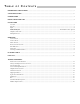
TABLE OF CONTENTS PERFORMANCE SPECIFICATIONS ............................................................................................................................... i SAFETY PRECAUTIONS ............................................................................................................................................... ii INTRODUCTION ........................................................................................................................................................
INTRODUCTION The Hafler P1500 and P3000 are two channel professional power amplifiers. Passive cooling with large heatsinks is used for low mechanical noise. Our patented trans•nova circuit topology and MOSFET output stage ensures trouble free, long term operation and is backed by our five year warranty. This manual contains information on using the P1500 and P3000 amplifiers. It is organized into three main sections. “Installation” covers the location and connection of the amplifier in the system.
Audio Ground Chass. Float –10 CH 2 –3 0dB –1 Mono 2-Ch 115V ~ 60Hz sig n al cl ip p i ng th er m a sh l or t Mono Output: • Use CH 1 Input ONLY • Set CH 2 Gain to Max • Set Output Level with CH 1 Gain Control channel 1 –15 –6 PUSH –2– trans nova 3 2 + CAUTION ! WARNING: DO NOT REMOVE COVER RISK OF ELECTRIC SHOCK DO NOT OPEN 4-8Ω CAUTION: For continued TO REDUCE THE RISK OF FIRE OR ELECTRIC SHOCK DO NOT EXPOSE THIS EQUIPMENT TO RAIN OR MOISTURE.
INSTALLATION LOCATION The P1500 and P3000 power transformer can generate a substantial magnetic field, so caution should be exercised in the placement of low level components such as a tape deck, mixer or mic preamp to avoid inducing noise in the low level circuitry. The amplifiers can also produce considerable heat in normal operation so the primary consideration when determining a location for the amplifiers is to allow for adequate ventilation.
INPUT The input jacks located on the back of the amplifier are dual function connectors which accept 1/4" Phone (Tip Ring Sleeve) or XLR plugs. The 1/4" Phone jack is connected according to conventional usage. The XLR jack is connected according to the IEC and AES standard.
SCHEMATIC DIAGRAM P3000 shown. Ground switch in Chassis position, Mono switch in 2-Channel position. P1500 differences shown on parts list.
Removable Center Spread
OUTPUT CONNECTIONS The speaker output connectors are dual binding posts. These binding posts will directly accept 12 AWG wire or banana plugs and are spaced on 3/4" centers to accept dual banana plugs. MONOPHONIC USE For systems with high power requirements, the amplifiers can be configured for single channel bridged mono operation. To bridge the amplifier, set the rear panel Mono/2 Channel switch to the Mono position.
SHORT CIRCUIT PROTECTION Due to the self-protecting properties of the output power MOSFETs, there is no need for sonically degrading voltage and current limiting circuits. To protect the amplifier from problems which may occur in the speaker line there is an overload detection circuit. ! In the event of a short in the speaker load or cables, the speaker detection circuit will shut down that channel and light the front panel SHORT indicator.
ROCKFORD CORP PC-0812-H M.
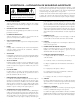
PARTS LIST P3000U 120VAC, 60Hz DESIGNATOR VALUE ALL RESISTORS IN OHMS, 1/4W PART # R1 R2 R3 R4 R5 R6 R7 R8 R9 R10 R11 R12 R13 R14 R15 R16 R17 R18 R19 R20 R21 R22 R23 R24 R25 R26 R27 R28 R29 R30 R31 R32 R33 R34 R35 R36 R37 R38 R39 R40 R41 R42 R43 R44 R45 R46 R47 R48 R49 R50 R51 R52 RMP/4-5622 RM/4-102C RM/4-473C RM/4-473C RM/4-472C RM/4-1071C RM/4-9090C RVH-201 RM/4-102C RMP/4-2802 RMP/4-106C RM/4-2802C RM/4-474C RM/4-160C RM/4-335C RM/4-472C RM/4-103C RM/4-104C RM/4-6043C RM/4-4532C RM/4-225C RM/4-104C R
DESIGNATOR C21 C22 C23 C24 C25 C26 C28 C29 C30 C31 C33 C35 C36 C112 C113 C114 C115 C116 C119 C120 VALUE 10µF, 16V 10µF, 16V 0.47µF, 50V 0.47µF, 50V 0.1µF, 50V 1µF, 50V 47µF, 16V 10µF, 50V 0.1µF, 50V 0.1µF, 50V 0.1µF, 50V 47pF, 200V 22pF, 200V 100µF, 25V 100µF, 25V 100pF, 50V 100pF, 50V 0.047µF, 50V 0.1µF, 100V 0.
TECHNICAL REFERENCE FIELD SERVICE CONSIDERATIONS A primary focus during the design and development of the P1500 and P3000 was to ensure the dependability of the amplifiers. The use of lateral MOSFET output transistors and the low voltage trans•nova input stage combined with careful component selection for the circuit assembly made the reliability goals achievable.
CIRCUIT OPERATION trans•nova Implementation: +18V Current Mirror Q104, Q105 Positive Buffer, DC Offset Integrator U2A, R11, C21, C22 Positive Input Buffer U1A Positive Output Q4, Q115 Positive Driver Cascode Q9, Q10 CMRR Adjust R8 B+ Drive Signal Local Feedback Balanced Signal Level Adjust R24 A, B Negative Input Buffer U1B + Differential Amp – Q6, Q7 Feedback Network Bias Adjust R136 Negative Buffer U2B Protection Switch, Soft Start Delay Q1, C29 Output Current Source Q103 Negative Drive
Output Short Protection Drive Signal Clip Detector U3A Shut Down Switch Q5, Q4 Comparator U3B Clip Detector U4A Short Latch U4C, CR14 Short Indicator CR1 Comparator U4A Output Signal The Short detector monitors the Drive Signal and Output Signal levels and shuts down that channel when a shorted output condition is detected. Recovering from the Short protection requires turning the amplifier off to reset.
Clipping Indicator Drive Signal Clipping Detector U5A LED Driver U5C CLIP Indicator CR3 The CLIP indicator is driven by the buffer U5C which is controlled by the comparator U5A. The voltage divider R56 and R57 establishes the reference voltage for the Clipping detector at pin 7 of U5A. The reference voltage scales the output of U5A to indicate when the Drive Signal at pin 6 demands in excess of the available voltage or current of the output stage.
amplifier. For a temporary adjustment when a signal generator and voltmeter are not available, use an FM tuner and tune it to an unused station as your signal source, and connect the output to the amplifier as described above. Connect the amplifier output to a small full range speaker. Turn the amplifier level controls full down and turn the amplifier on. Turn up the level control until you hear a signal through the speaker. Alternate adjusting R8 and the input control until you have the level control full.
SERVICE POLICY AND LIMITED WARRANTY Rockford Corporation (Hafler Division) offers a limited warranty on Hafler products on the following terms: • Length of Warranty 5 years on P1000, P1500, P3000, P4000 7 years on P9505 and P7000 90 days on all B-Stock (receipts are required) • What is Covered This warranty applies only to products sold to the original owner (non-transferable). This only applies to units sold in the Continental United States.
NOTES
® HAFLER A DIVISION OF ROCKFORD CORPROATION 546 SOUTH ROCKFORD DRIVE TEMPE, ARIZONA 85281 U.S.A. 480-967-3565 / 1-888-HAFLER1 WWW.HAFLER.COM MAN-1461-C 4/99 E.W.R.