P7000 Installation & Operation ® ® a v o n s n a r t D AS ESIG SEM NE BLE D A D I ND NT HE U SA PROFESSIONAL POWER AMPL AMPLIFIER
NOTICE - IMPORTANT SAFETY INFORMATION CAUTION RISK OF ELECTRIC SHOCK DO NOT OPEN The lightning flash with arrowhead symbol within an equilateral triangle is intended to alert the user to the presence of uninsulated "dangerous voltage" within the product's enclosure, that may be of sufficient magnitude to constitute a risk of electric shock to persons. ! WARNING: TO PREVENT FIRE OR SHOCK HAZARD, DO NOT EXPOSE THIS EQUIPMENT TO RAIN OR MOISTURE.
PERFORMANCE SPECIFICATIONS P7000 Power Rating: FTC (20Hz-20kHz, <0.1% THD) EIA (1kHz, 0.1% THD) 350 wpc into 8Ω 375 wpc into 8Ω 500 wpc into 4Ω* 525 wpc into 4Ω* 1000 wpc into 8Ω* 1050 wpc into 8Ω* *Continuous sine wave power limited by current rating of line fuse. Signal-to-Noise: 100dB below rated output from 20Hz to 20kHz Frequency Response: ±0.1dB, 20Hz to 20kHz +0/–3dB, 0.
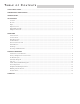
TABLE OF CONTENTS SAFETY PRECAUTIONS ........................................................................................................................................... i PERFORMANCE SPECIFICATIONS ......................................................................................................................... ii INTRODUCTION ...................................................................................................................................................
INTRODUCTION The Hafler P7000 is a two channel professional power amplifier suitable for use in any sound reinforcement situation where faithful, accurate reproduction is required. The amplifier uses forced air fan cooling to deliver high power output in a compact size. Status indicators on the front panel give a visual representation of amplifier and system operation.
INSTALLATION LOCATION The P7000 uses forced-air fan cooling to remove the heat produced in normal operation. Although this makes the amplifier less sensitive to ventilation than if it were passively cooled, fresh air flow at the mounting location must still be considered. The fan pulls in fresh air through the side vents and the heated air is forced out through the front panel. Another consideration when choosing the location for a fan cooled amplifier is its proximity to the listening position.
INPUT CROSSOVER The XCard crossover modules are plug-in cards located inside the amplifier. The P7000 is shipped with 100Hz XCards in each channel. Since each XCard can operate full range, high-pass or low-pass, with a 12dB per octave slope, this allows the amplifier to be used in a wide range of applications. XCards are available for a variety of frequencies from your dealer or through our Customer Service department. To order additional XCards call Customer Service at 800-669-9899.
OPERATION POWER SWITCH The POWER switch is located on the front panel of the amplifier. An internal lamp indicates when it is turned on. Standard practice is to turn the amplifier on last and off first when switching components individually to prevent sending damaging transients, generated in the source components, to the speakers. It is possible to leave the power switch in the on position and switch the amplifier remotely through a power distribution block or preamp switched outlet.
GROUND SWITCH Ground loops are characterized by a hum or buzz through the speakers and are caused by a voltage potential difference between two points in a ground circuit. Ground loops are aggravated when multiple paths exist for a given circuit. Mounting components in a rack with metal rails may introduce ground loops between associated equipment, because the rails can establish an additional ground path.
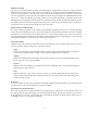
TECHNICAL REFERENCE FIELD SERVICE CONSIDERATIONS A primary focus during the design and development of the P7000 was to ensure the dependability of the amplifiers. The use of lateral MOSFET output transistors and the low voltage trans•nova input stage combined with careful component selection for the circuit assembly made the reliability goals achievable.
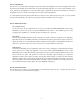
PC BOARD LAYOUT –7–
PARTS LIST DESIGNATOR VALUE ALL RESISTORS IN OHMS PART # R1 R2 R3 R4 R5 R6 R7 R8 R9 R10 R11 R12 R13 R14 R15 R16 R17 R18 R19 R20 R21 R22 R23 R24 R25 R26 R27 R28 R29 R30 R31 R32 R33 R34 R35 R36 R37 R38 R39 R40 R41 R42 R43 R44 R45 R46 R47 R48 R49 R50 R51 R52 R53 R54 R55 R56 R57 R58 R59 R60 R61 R62 R63 R64 R65 R66 R67 R68 R69 RMP/4 5622-03 RM/4-102C RM/4-473C RM/4-473C RM/4-102C RM/4-2800C RM/4-2151C RVH-201 RM/4-2261C RMP/4-2802 RM/4-304C RM/4-2802C RM/4-474C RM/4-101C RM/4-335C RM/4-472C RM/4-103C RM/4-104
DESIGNATOR VALUE PART # DESIGNATOR VALUE PART # C21 C22 C23 C24 C25 C26 C27 C28 C29 C30 C31 C32 C33 C34 C35 C36 C37 C38 C39 C40 C42 C43 C44 C45 C46 C47 C48 C49 C50 C112 C113 C114 C115 C116 C119 C120 10µF, 16V, Electrolytic 10µF, 16V, Electrolytic 0.47µF, 50V 0.47µF, 50V 0.1µF, 50V 0.1µF, 50V 4700µF, 100V, Electrolytic 47µF, 16V, Electrolytic 10µF, 50V, Electrolytic 0.1µF, 50V 0.1µF, 50V 27pF, 50V 0.1µF, 50V 27pF, 50V 22pF, 500V, Mica 47pF, 500V, Mica 0.1µF, 50V 0.1µF, 50V 1.0µF, 50V, Electrolytic 0.
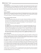
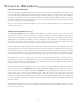
P7000 F UNCTIONAL B LOCK D IAGRAM Driver Cascode Q9, Q10 Current Mirror Q104, Q105 XCard Output Q30, Q31, Q32, Q33 B+ +94V Crossover U7A Level Control R24 Positive Input Buffer U1A DIABLO R73, CR16 Q17, Q18 Input Buffer U2a Bias Adjust R136 Local Feedback CMRR Adjust R8 Balanced Signal Differential Amp Q6, Q7 Feedback Network Output DC Offset Integrator U2B, C22, C21, R11 Negative Input Buffer U1B Crossover U7B XCard Soft Start Switch Delay Q1, C29, R13 Current Source Q103 – 12 – Driver
CIRCUIT OPERATION trans•nova Implementation The transistor Q1 is configured to operate as a switch which controls the current source, Q103, of the input differential amp, Q6 and Q7. When Q1 is off the emitter voltage is low turning off Q103. Timing of the Soft Start function is controlled by the charging time of C29 through R13. The THERMAL Protection circuit uses Q1 to shut down the channel when excessive heat is detected.
Fan Speed Regulation Driver U9A Fan Drive Amp Q20, Q19 Temp TS1, R25 Trip Switch U9B Cooling air for each channel is provided by a DC fan. The fan is configured to track the heatsink temperature, and increases in speed as the amplifier runs hotter. The heatsink temperature, Temp, is determined by the voltage divider TS1 and R25.
Thermal Protection Soft Start Switch Q1 Temp TS1, R25 Comparator U5B THERMAL Indicator CR2 The Thermal protection is activated, and shuts down audio operation, when the amplifier heatsink reaches an excessively high temperature. The voltage divider R22 and R23 establishes the reference voltage on pin 5 of U5B. The control voltage, Temp, on pin 4 is established by the voltage divider TS1 and R25. TS1 is a NTC (Negative Temperature Coefficient) thermistor, mounted on the heatsink.
AMPLIFIER MODULE REPLACEMENT The amplifier modules have been designed to eliminate the need for a special workplace if a field exchange becomes necessary. All wire connections are made with quick connect terminals so soldering is not necessary. The following tools are needed to disassemble the amplifier: Allen wrench, 9/64 Phillips screwdriver, #1 tip Thin nose pliers Small cutters Remove the four Phillips head screws, located on the rear panel, which secure the input jacks.
BUILDING CUSTOM XCARDS The XCard crossover control modules used in the P7000 are a versatile and inexpensive method for configuring the amplifier for a wide range of system applications. The XCard eliminates the need for an external crossover or expensive plug-in accessories for multiple amp applications.
RESISTOR CHART The following charts list the resistor values to use for common crossover frequencies. Butterworth Alignment Q = .707 Butterworth Alignment Q = .707 1% resistors used with 0.047µF capacitors 1% resistors used with 0.022µF capacitors Frequency 20Hz 25Hz 30Hz 35Hz 40Hz 45Hz 50Hz 55Hz 60Hz 65Hz 70Hz 75Hz 80Hz 84Hz 90Hz 200Hz 300Hz 400Hz 500Hz 600Hz 700Hz 800Hz 900Hz 1kHz 1.2kHz 2kHz 3kHz 4kHz 5kHz 6kHz 7kHz 8kHz R1 169kΩ 133kΩ 110kΩ 95.3kΩ 84.5kΩ 75kΩ 68.1kΩ 61.9kΩ 56.2kΩ 52.3kΩ 48.7kΩ 45.
SERVICE POLICY AND LIMITED WARRANTY If you encounter any difficulty or have any question concerning your P7000 Amplifier, please call our Technical Support Department weekdays, 8:00 a.m. to 3:30 p.m., Mountain Standard Time, at 800-743-3526. Should you have any doubts as to whether the amplifier is malfunctioning and requires service, please call us before sending it in for repair. All units being returned (regardless of warranty status) must receive a Return Authorization (RA) number.
HAFLER PROFESSIONAL A DIVISION OF ROCKFORD CORPORATION 546 SOUTH ROCKFORD DRIVE TEMPE, ARIZONA 85281 U.S.A. IN U.S.A.