Declaration of Conformity Application of Council Directive: 73/23/EEC (low voltage directive) Standard(s) to which Conformity is Declared: EN55013-1 EN55103-2 EN60065 (safety) Manufacturer’s Name: Hafler Manufacturer’s Address: 546 South Rockford Drive, Tempe, Arizona 85281 Importer’s Name: ________________________________________________________ Importer’s Address: ________________________________________________________ Type of Equipment: 2-channel Audio Power Amplifier/Speaker Model No.
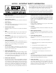
NOTICE - IMPORTANT SAFETY INFORMATION The lightning flash with arrowhead symbol within an equilateral triangle is intended to alert the user to the presence of uninsulated "dangerous voltage" within the product's enclosure, that may be of sufficient magnitude to constitute a risk of electric shock to persons.
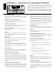
ESPAÑOL ADVERTENCIA – INFORMACION DE SEGURIDAD IMPORTANTE El símbolo de flecha relámpago dentro de un triángulo equilátero, es para alertar al usario de la presencia de “voltajes peligrosos” no aislados en el interior del aparato, los cuales pueden ser de suficiente magnitud para constituir un riesgo de choque eléctrico a las personas.
FRANÇAIS ATTENTION: INFORMATIONS IMPORTANTES DE SÉCURITÉ La lumière clignotante du symbole de la flêche à l'intérieur d'un triangle équilatéral, à pour objet d'alerter l'utilisateur de la présence “d'un voltage dangereux” non-isolé à l'intérieur du produit, qui pourrait être de magnitude suffisante au risque d'éléctrocution.
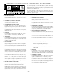
DEUTSCH ACHTUNG – WICHTIGE SICHERHEITS – INFORMATIONEN Der Blitz mit dem Pfeil, in einem gleihschenkligen Dreieck, soll den benutzer vor unisolierter “gefährlicher Spannung” innerhalb des Gerätes warnen. Das Ausrufezeichen, in einem gleichschenkligen Dreieck, soll den Benutzer darauf aufmerksam machen, daβ dem Gerät wichtige Operations - und Service - Informationen beigefügt sind. 1.
ITALIANO NOTARE – IMPORTANTI INFORMAZIONI SULLA SICUREZZA Il simbolo del fulmine in un triangolo equilatero vuole avvertire della presenza di tensioni elevate non isolate e di valore sufficiente per costituire rischio di shock elettrico alle persone. Il punto esclamativo contentuto in un triangolo equilatero vuole avvertire l'utente della presenza di parti di servizio e di manutenzione che sono dettagliate nel manuale di istruzioni. 1. 2.
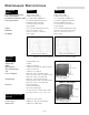
PERFORMANCE SPECIFICATIONS SUBWOOFER MODEL Free Field Frequency Response Peak Acoustic Output Total Harmonic Distortion (THD) Low Frequency Driver Cabinet Dimensions Net Weight TRM10.1 TRM12.1 27Hz–110Hz, ±2dB ≥112dB (w/music @ 2m) <3%, 30Hz–90Hz (90dB @ 2m) 10" (254mm) Cellulose Fibre Cone Santoprene Rubber Surround 2" (51mm) 4-Layer Voice Coil 30 oz. Magnet 1.0ft3 (28 Liter) Vented Down Firing 14.75"(H) x 16"(W) x 16"(D) (37.46cm x 40.64cm x 40.64cm) 53 lbs.
TABLE OF CONTENTS SAFETY PRECAUTIONS ..........................................................................................................................................i PERFORMANCE SPECIFICATIONS Frequency Response Graphs ......................................................................................................................vi INTRODUCTION ..................................................................................................................................................
INTRODUCTION Thank you and congratulations on your purchase of the HAFLER TRM10.1/TRM12.1 reference monitor, the world's finest brand in professional audio equipment. The TRM10.1 (Trans•ana Reference Monitor) is an amplified 10" subwoofer monitor. The TRM12.1 is an amplified 12" subwoofer monitor. Both models offer unmatched quality and performance in a truly professional grade product. The TRM10.1/TRM12.1 are great for Professional Studios, Digital Work Stations, Broadcast Booths, and Home Project Studios.
Amplifier MEHSA (Maximum Efficiency HeatSink Application) MEHSA is a proprietary process that yields up to 5 times better heat transfer than traditional FET mounting techniques using the exact same components. A multi-layer insulated metal substrate operating with minimal thermal resistance spreads heat both downward and outward to quickly dissipate heat from each device across the heatsink.
Subsonic Filter The TRM series uses a Subsonic Filter to prevent the woofer from reproducing inaudible frequencies. Subsonic frequencies (known as infrasonic frequencies) are signals below the normal human hearing range and are generally considered to be below 20Hz. The subsonic filter reduces the energy of these frequencies and restrains the woofer from operating outside its optimum linear excursion.
TRM10.1 TRM12.
SCHEMATIC DIAGRAM NOTES: Unless specified otherwise 1. All resistors in ohms. 2. All capacitors in microfarads.
Qualified Service Personnel Only Input Circuit / Power Supply Schematic –6–
SCHEMATIC DIAGRAM NOTES: Unless specified otherwise 1. All resistors in ohms. 2. All capacitors in microfarads.
Qualified Service Personnel Only Output Circuitry –8–
INSTALLATION LOCATION The acoustic properties and size of the listening environment can drastically influence the SPL (Sound Pressure Level) and f3 (-3dB roll-off) of the subwoofer. However it's important to note that large or small acoustic spaces have little to no effect on the subwoofer cone excursion & box "Q." For the most part, we'll discuss the optimum location for two different installation methods: Studio Installation and Home Theater Installation.
INPUT SWITCH The unbalanced input uses a conventional RCA phone jack. Move the input switch to RCA UNBALANCED to use this jack. The balanced input jack is an XLR plug. The XLR jack is connected according to the IEC and AES standard. Move the input switch to XLR BALANCED to use this jack.
OPERATION AUTO TURN-ON / SLEEP MODE The TRM10.1/TRM12.1 subwoofers automatically turn on when they sense an input signal. When the signal being fed to the TRM10.1/TRM12.1 is turned off, the subwoofer's amplifier will turn off and go into "sleep mode." This feature eliminates the inconvenience of operating a mechanical switch. INPUT SENSITIVITY (GAIN) The Input Sensitivity is used to match the TRM10.1/TRM12.1 with signal levels from a variety of mixing consoles.
PHASE CONTROL The Phase Control switches allow the TRM10.1/TRM12.1 to be acoustically aligned with other speakers in your system. 0˚, -270˚, -180˚, or -90˚ of phase shift at 80Hz can be selected using DIP switches 2, 3, and 4. For 0˚ of phase shift, leave all three switches in the OFF (up) position. -270˚ of phase shift occurs when switch 2 is selected in the ON (down) position. -180˚ can be achieved by selecting both switches 2 and 3 in the ON (down) position.
AC LINE The TRM10.1 /TRM12.1 operate from a 115 VAC/60Hz power line. The TRM10.1SCE/TRM12.1SCE operate from a 230 VAC 50/60Hz power line. Connection is made by a 16-gauge, IEC Type 320, grounded line cord. For safety considerations only a properly grounded (earthed) receptacle should be used. If a grounded circuit is not available, do not break off the ground pin; use the proper adapter plug for a two wire receptacle with the grounding plug suitably connected to earth ground.
PC BOARD LAYOUT Qualified Service Personnel Only – 14 –
PARTS LIST DESIGNATOR VALUE ALL RESISTORS IN OHMS PART # R1 R10 R100 R101 R102 R103 R104 R107 R109 R11 R110 R111 R112 R113 R114 R12 R120 R121 R122 R123 R124 R125 R127 R129 R13 R130 R132 R136 R137 R14 R145 R146 R147 R15 R156 R157 R158 R16 R164 R17 R18 R19 R2 R20 R21 R22 R23 R24 R25 R26 R27 R278 R28 R29 R29 R3 R30 R31 R32 R33 R34 R35 R36 R37 R38 R39 R4 R40 RM/10-1001B RM/10-473B RM/10-1002B RM/10-9091B RM/10-105B RM/10-1002B RM/10-133B RM/10-1002B RM/10-1402B RM/10-1001B RM/10-1402B RM/10-1402B RM/10-133B
C23 C24 C29 C3 C30 C31 C32 C33 C34 C35 C36 C37 C38 C39 C4 C40 C41 C42 C43 C44 C45 C46 C47 C48 C5 C51 C52 C53 C55 C56 C57 C58 .47UF 50V .1UF 50V 10UF 16V .1UF 50V 10UF 16V .1UF 50V CAP 3300UF 63V 100PF 50V 47PF 100V CAP 3300UF 35V .1UF 50V CAP 3300UF 63V 47PF 100V 47PF 100V .1UF 50V 220PF 50V 220PF 50V .1UF 50V .01UF 50V 100PF 50V .1UF 50V .22UF 50V .1UF 50V .1UF 50V .1UF 50V .47UF 50V .47UF 50V .1UF 50V .1UF 50V .1UF 50V .1UF 50V .
TRM10.1/12.1 FUNCTIONAL BLOCK DIAGRAMS Qualified Service Personnel Only INPUT CIRCUIT The stereo input signals are connected to the amplifier through balanced XLR connectors, or unbalanced RCA connector TP2. Unbalanced operation can be selected with switch DS1, which grounds the RCA shell through R37. Input buffers U1 and U10 provide a stable input impedance, dominated by R10, R4, R42, and R32.
Qualified Service Personnel Only CLASS-G TRANS•ANA AMPLIFIER The transistor Q8 is configured as a switch, which controls the current source Q5, of the input differential amplifier Q11 and Q12. If the power On/Off, Signal Sensing, and Thermal Protection circuits have all stopped pulling to -15V, the turn-on process begins, and the voltage at the emitter of O8 slowly ramps up to zero Volts according to the charging time of soft start components R13, C93, and C94.
Qualified Service Personnel Only POWER ON/OFF CIRCUIT The power on/off circuit is designed to turn the amplifier on slowly and off quickly. When AC power is initially applied to the subwoofer, AC signals on the secondary of the power transformer are negatively rectified through CR2 and CR7 into peak holding capacitor C31, and divided by R19 and R20. When the resulting DC voltage at pin 2 of U15A is lower than the -1.
Qualified Service Personnel Only CIRCUIT CALIBRATION Bias: The bias control establishes the quiescent Class AB output current of the amplifier. The bias should not need readjustment from the factory setting; however, if the amplifier is repaired and the output devices have been changed, calibrating the bias is necessary. Disconnect the power to the amplifier before removing the heatsink assembly from the speaker cabinet.
Qualified Service Personnel Only AMPLIFIER REPLACEMENT 1. 2. 3. 4. 5. 6. Remove (10) screws from amplifier using a Phillips screwdriver Remove amplifier from enclosure Disconnect the (2) speaker wires (FIG. 1) Disconnect the transformer primary molex (FIG. 1) Disconnect the transformer secondary molex (FIG. 1) Follow steps 1-5 in reverse order to install amplifier CAUTION: Reconnect wires as indicated in diagram! FIG. 1 Amplifier Replacement WOOFER REPLACEMENT 1. 2. 3. 4.
SERVICE POLICY AND LIMITED WARRANTY Rockford Corporation (Hafler Division) offers a limited warranty on Hafler products on the following terms: • Length of Warranty 1 year on Subwoofer Monitors • What is Covered This warranty applies only to products sold to the original owner and is non-transferable. This warranty only applies to units sold in the continental United States. You are required to have a copy of the receipt stating the customer's name, dealer name, product purchased and date of purchase.
HAFLER A DIVISION OF ROCKFORD CORPORATION 546 SOUTH ROCKFORD DRIVE TEMPE, ARIZONA 85281 U.S.A. 1.866.GOHAFLER 480.967.3565 WWW.HAFLER.COM MADE IN THE USA This product is designed, developed and assembled in the USA by a dedicated group of American workers. The majority of the components used in the construction of this product are produced by American companies.