Declaration of Conformity Application of Council Directive: 73/23/EEC (low voltage directive) Standard(s) to which Conformity is Declared: EN55103-1 EN55103-2 EN60065 (safety) Manufacturer’s Name: Hafler Manufacturer’s Address: 546 South Rockford Drive, Tempe, Arizona 85281, U.S.A.
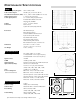
PERFORMANCE SPECIFICATIONS TRM6.1 Free Field Frequency Response Peak Acoustic Output Total Harmonic Distortion (THD) High Frequency Driver Low Frequency Driver Cabinet Front Panel: Rear Panel: Dimensions Net Weight AMPLIFIER SECTION Power Rating Signal-to-Noise CMRR Input Impedance Input Sensitivity Range Gain Power Consumption (both channels driven) 55Hz–21kHz, ±2dB ≥119dB (per pair w/music @ 1m) <0.5%, 150Hz–21kHz (90dB @ 1m on axis) 1" (25mm) Vifa Soft Dome 6.
NOTICE - IMPORTANT SAFETY INFORMATION CAUTION RISK OF ELECTRIC SHOCK DO NOT OPEN The lightning flash with arrowhead symbol within an equilateral triangle is intended to alert the user to the presence of uninsulated "dangerous voltage" within the product's enclosure, that may be of sufficient magnitude to constitute a risk of electric shock to persons.
ESPAÑOL ADVERTENCIA – INFORMACION DE SEGURIDAD IMPORTANTE El símbolo de flecha relámpago dentro de un triángulo equilátero, es para alertar al usario de la presencia de “voltajes peligrosos” no aislados en el interior del aparato, los cuales pueden ser de suficiente magnitud para constituir un riesgo de choque eléctrico a las personas.
FRANÇAIS ATTENTION: INFORMATIONS IMPORTANTES DE SÉCURITÉ La lumière clignotante du symbole de la flêche à l'intérieur d'un triangle équilatéral, à pour objet d'alerter l'utilisateur de la présence “d'un voltage dangereux” non-isolé à l'intérieur du produit, qui pourrait être de magnitude suffisante au risque d'éléctrocution.
DEUTSCH ACHTUNG – WICHTIGE SICHERHEITS – INFORMATIONEN Der Blitz mit dem Pfeil, in einem gleihschenkligen Dreieck, soll den benutzer vor unisolierter “gefährlicher Spannung” innerhalb des Gerätes warnen. Das Ausrufezeichen, in einem gleichschenkligen Dreieck, soll den Benutzer darauf aufmerksam machen, daβ dem Gerät wichtige Operations - und Service - Informationen beigefügt sind. 1.
ITALIANO NOTARE – IMPORTANTI INFORMAZIONI SULLA SICUREZZA Il simbolo del fulmine in un triangolo equilatero vuole avvertire della presenza di tensioni elevate non isolate e di valore sufficiente per costituire rischio di shock elettrico alle persone. Il punto esclamativo contentuto in un triangolo equilatero vuole avvertire l'utente della presenza di parti di servizio e di manutenzione che sono dettagliate nel manuale di istruzioni. 1. 2.
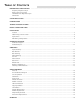
TABLE OF CONTENTS PERFORMANCE SPECIFICATIONS ........................................................................................................................i Frequency Response Graph Energy Time Curve Graph Horizontal Polar Response Graph Dimensions SAFETY PRECAUTIONS ..........................................................................................................................................ii INTRODUCTION ................................................................................
INTRODUCTION Thank you and congratulations on your purchase of the HAFLER TRM6.1 reference monitor, the world's finest brand in professional audio equipment. The TRM6.1 (Trans•ana Reference Monitor) is a bi-amplified, two-way near field monitor offering unmatched quality and performance in a truly professional grade product. The TRM6.1 is great for Professional Studios, Digital Work Stations, Broadcast Booths, and Home Project Studios.
Amplifie MEHSA (Maximum Efficiency HeatSink Application) MEHSA is a proprietary process that yields up to 5 times better heat transfer than traditional FET mounting techniques using the exact same components. A multi-layer insulated metal substrate operating with minimal thermal resistance spreads heat both downward and outward to quickly dissipate heat from each device across the heatsink.
Tweete Wave Guide The wave guide is a proprietary axis-symmetrical form of horn mounted to the tweeter to increase efficiency. The wave guide improves the transition of sound waves (from planar to spherical) smoothly from the throat of the wave guide to the mouth. The unique shape and smooth surfaces improve the tweeter's off-axis frequency response as well as provide coherent on-axis response. THE RESULT: Improves dispersion for a wider “sweet spot.
Front Panel View Rear Panel View Tweeter Wave Guide Status LED Power Switch Balanced Input Unbalanced Input Input Switch Sensitivity Bass Roll Off Bass Shelving –4– Treble Shelving Woofer Heatsink AC Line Input AC Line Fuse Rubber Pad
INSTALLATION LOCATION The location of your reference monitors in addition to the acoustics of the listening room will influence the system frequency response. In the near field environment, our ears are more sensitive to direct sound rather than the reverberation of sound. Below are some recommendations for the initial set-up which may help you optimize performance in complex acoustic environments. In any configuration, keep the rear of the monitor at least 5" (12.
DETERMINING ACOUSTIC CENTER Finding the “Acoustic Center” is accomplished by positioning the monitors so coherent arrival of the transducers occurs at ear level. The Acoustic Center is located 3 to 4 feet in front of the monitor, measuring perpendicularly from the center point of the cabinet (midway between the woofer and tweeter).
SCHEMATIC DIAGRAM NOTES: Unless specified otherwise 1. All resistors in ohms. 2. All capacitors in microfarads. 3. Channel 1 only shown.
Qualified Service Personnel Only –8–
SCHEMATIC DIAGRAM NOTES: Unless specified otherwise 1. All resistors in ohms. 2. All capacitors in microfarads. 3. Channel 1 only shown.
Qualified Service Personnel Only –10–
Qualified Service Personnel Only SCHEMATIC Diagram NOTES: Unless specified otherwise 1. All resistors in ohms. 2. All capacitors in microfarads. 3. Channel 1 only shown.
PC BOARD LAYOUT Qualified Service Personnel Only – 12 –
OPERATION NOTE: When using the INPUT SENSITIVITY, select only one switch configuration at a time. Engaging multiple switch configurations (i.e., moving two or more switches ON) may cause undesirable operation and is NOT RECOMMENDED. INPUT SENSITIVITY The Input Sensitivity adjustment is used to match the monitor with signal levels from a variety of mixing consoles. The Input Sensitivity uses DIP switches to match input levels over a 15dB range and are marked +1dB, –2dB, –5dB, –8dB, and –11dB.
NOTE: When using the BASS SHELVING & TREBLE SHELVING, select only one switch configuration at a time. Engaging multiple switch configurations (i.e., moving two or more switches ON) may cause undesirable operation and is NOT RECOMMENDED. BASS SHELVING Bass Shelving is used to match the low frequency response of the monitor to the acoustic environment. Bass Shelving uses DIP switches to control frequencies from 40Hz to 200Hz over an 8dB range and are marked +4dB, +2dB, –2dB, and –4dB.
POWER SWITCH The POWER switch is located on the front panel. The LED will illuminate GREEN, indicating the respective amplifiers are on. It is possible to leave the power switch in the ON position and switch the monitor remotely through a power distribution block or switched outlet. When doing so, make sure the switch is rated for the current required by the monitor.
PARTS LIST DESIGNATOR VALUE ALL RESISTORS IN OHMS PART # R1 R10 R102 R103 R104 R105 R106 R107 R108 R109 R11 R110 R111 R112 R113 R114 R115 R116 R117 R118 R119 R12 R120 R121 R122 R123 R124 R125 R128 R129 R13 R130 R131 R132 R133 R134 R135 R136 R137 R138 R139 R14 R140 R141 R142 R143 R144 R145 R146 R147 R148 R15 R150 R151 R154 R156 R16 R163 R164 R165 R166 R167 R169 R17 R170 R171 R172 R173 RM/10-1001B RM/10-473B RM/4-682C RM/4-682C RV-502Q RM/10-1001B RM/10-3572B RM/10-3572B RM/10-3572B RM/10-1402B RV-202 RM/1
R70 R71 R72 R73 R74 R75 R76 R78 R79 R8 R80 R81 R82 R84 R85 R86 R87 R88 R89 R9 R90 R91 R92 R93 R94 R95 R96 R97 R98 R99 RES 280 OHM 1/10W 1% RES 10 OHM 1/10W 5% RES 100 OHM 1/4W 5% RES 2.21K OHM 1/10W 1% RES 2.21K OHM 1/10W 1% RES 100K OHM 1/10W 5% 619K OHM 1/10W 1% RES 1M OHM 1/10W 5% RES 1M OHM 1/10W 5% POT 2K TRIM RES 6.49K OHM 1/10W 1% RES 6.49K OHM 1/10W 1% 46.4K OHM RES. 1/10 W 1% RES 120 OHM 1/10W 5% 46.4K OHM RES. 1/10 W 1% RES 5.49K OHM 1/10W 1% RES 1.62K OHM 1/4W 1% RES 2.0K OHM 1/10W 1% RES 2.
Q3 Q30 Q31 Q32 Q33 Q35 Q37 Q38 Q39 Q5 Q6 Q7 Q8 Regulator LM337 XSTR MMBT5088L NPN XSTR MMBT5088L NPN XSTR MMBT3906LT1 PNP XSTR MMBT3906LT1 PNP XSTR MMBT3906LT1 PNP XSTR MPS6521 XSTR MMBT3906LT1 PNP XSTR MMBT3906LT1 PNP XSTR MMBTA06L XSTR MMBT3906LT1 PNP XSTR MMBT3906LT1 PNP XSTR MMBT3904LT1 NPN SS-1376 SS-0114 SS-0114 SS-0791 SS-0791 SS-0791 SS-209 SS-0791 SS-0791 SS-102SM SS-0791 SS-0791 SS-0792 U1 U112 U2 U3 U4 U5 U7 U8 OPAMP TL072CD OPAMP TL072CD OPAMP TL072CD OPAMP TL072CD OPAMP TL072CD COMPTR QUAD
TRM6.
SERVICE REFERENCE CIRCUIT OPERATION Qualified Service Personnel Only trans•ana Implementation The transistor Q24 is configured to operate as a switch that controls the constant current source Q21 of the differential amplifier Q27 and Q28. Switch Q24 is under the control of the thermal and turn-on circuits, and provides a Soft Start turn-on ramp according to the charging time of C70 through R13 and R156. U8B is configured as a DC servo-integrator to null the output offset voltage.
Input Circuit Qualified Service Personnel Only The input signal is connected to the amplifier through the balanced XLR connector J1, or the unbalanced RCA connector J2. Balanced/unbalanced switch DS1 will ground the inverting input buffer, allowing operation with an unbalanced signal on either connector. Input buffers U1A and U1B provide a stable input impedance, dominated by R10 and R4. The input circuit gain is set by switches DS2-DS6.
Qualified Service Personnel Only Woofer Crossover The input signal at U4A pin 1 connects to the 3200Hz 2nd order low-pass filter at U112B. Approximately 2dB of additional gain can be added to this stage by adjusting R136 against the divider resistor, R137. The next stage is a 30Hz–60Hz switchable sub-sonic high-pass filter. This is followed by an adjustable low-frequency shelving filter which defaults at +6dB gain, according to the feedback resistors R129 and R134, and dividers R131 and R128.
Qualified Service Personnel Only Clipping Indicator The CLIP indicators are driven by the comparator U5A and U5D. The voltage divider R56, R57, and R51, R61 establishes the reference voltage for the Clipping detector at pin 7 of U5A and pin 9 of U5D. Excessive drive signal at pin 6 or pin 8 will trigger its comparator low and light the CLIP/THERMAL indicator red. On Indicator The bicolor LED, CR3, will remain green unless a THERMAL or CLIP condition is detected.
Qualified Service Personnel Only TWEETER REPLACEMENT 1. 2. 3. 4. 5. 6. 7. 8. 9. Remove (4) screws from wave guide using a 3/32" Allen Wrench Remove wave guide assembly from enclosure Disconnect the LED harness (FIG. 1) Disconnect the (2) speaker wires from the tweeter (FIG. 2) Disconnect the (2) power switch wires (FIG.
Qualified Service Personnel Only AMPLIFIER REPLACEMENT 1. Remove (2) screws from back using a 3/32" Allen Wrench (FIG. 5) 2. Disconnect PCB mounted LED harness (FIG. 6) 3. Disconnect PCB mounted tweeter speaker wires (FIG. 7) 4. Disconnect PCB mounted woofer speaker wires (FIG. 7) 5. Disconnect PCB mounted transformer primary wires (FIG. 8) 6. Disconnect PCB mounted transformer secondary wires (FIG. 8) 7. Disconnect PCB mounted power switch wires (FIG.
SERVICE POLICY AND LIMITED WARRANTY Rockford Corporation (Hafler Division) offers a limited warranty on Hafler products on the following terms: • Length of Warranty 1 year on Reference Monitors • What is Covered This warranty applies only to products sold to the original owner and is non-transferable. This warranty only applies to units sold in the continental United States. You are required to have a copy of the receipt stating the customer's name, dealer name, product purchased and date of purchase.
HAFLER A DIVISION OF ROCKFORD CORPORATION 546 SOUTH ROCKFORD DRIVE TEMPE, ARIZONA 85281 U.S.A. 1.866.GOHAFLER 480.967.3565 WWW.HAFLER.COM MADE IN THE USA This product is designed, developed and assembled in the USA by a dedicated group of American workers. The majority of the components used in the construction of this product are produced by American companies.