
Service Manual


CONSOLE TECHNICAL OVERVIEW
I-9
ENGLISH
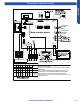
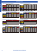
Wiring Diagram/DIP Switch Settings
USYF09UCDWA1
Note:
1.Dashed parts are optional.
2.Please refer to the technical service manual for detailed explanations
of DIP switches.
3.Do not change the DIP switches setting without technical support
4.Abbreviation:R-red ,B-black,BL-blue,W-white,Y/G-yellow/green,
TEMP.-temperature, E.A.O-exrernal alarm output,Tr-indoor unit
room temperature sensor ,Tp-indoor unit pipe temperature sensor (coil
temperature sensor)
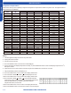
Wired controller
display(YR-E17)
07 flashing on the
upper right corner
Outdoor error code
+20 correspond
HEX code
Tp
Tr
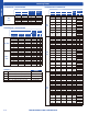
SW1-1
OFF
OFF
SW1-2
OFF
OFF OFF
OFF
OFF
OFF
OFF
OFF
OFF OFF
OFF
OFF
OFF
ON
OFF
OFF OFF
OFF
OFF
OFFOFF
ON
SW1-3
SW1-4
SW1-5 SW1-6
SW1-7 SW1-8
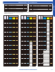
To Outdoor Unit
All Console
default
MODEL
DIP switches factory default setting
L2
L1
Note:
SW1
LED5
LED4
250VAC T5A
FUSE
CN20
CN22(22-1)
CN31
CN11
CN35
Main control board
Swing motor
for lower
louver
Swing motor
for upper
louver
CN10
CN6
CN3
CN17
SW2
CN16
CN16-1
W
B
W
BL
BL
W
W
W
YL
BL
W
W
Panel
display
RJ45 BOARD
To RJ45 DEVICE
SW3-1
SW3-2 SW3-3
SW3-4
SW3-5 SW3-6
SW3-7 SW3-8
USYF12UCDWA1
USYF18UCDWA1