
Service Manual


OUTDOOR TECHNICAL OVERVIEW
B-4
ENGLISH
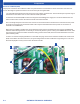
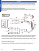
Components
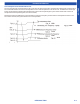
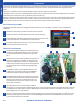
1. A replaceable 25A 250V rated ceramic fuse protects the outdoor unit electronics. The fuse would open if a power surge or
internal short in the outdoor unit occurred. This fuse is eld replaceable.
2. The Power Circuit Board (PCB) receives line voltage from the building power supply via a connection between the Line
Power terminal on the outdoor unit and the terminals P1 and P2 of the PCB.
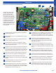
345. The voltage that powers the indoor units connects to terminals P3 and P4. The Electronic Control Unit receives power
to operate via connections at terminals P5 and P6. The Compressor Module board receives power via connections at
terminals P7 and TERMINAL 3.
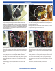
When power is available to the Electronic Control Board and the Compressor Module board, their respective GREEN LED
indicators will be ashing if the unit is in standby, or continuously lit if the system is running. If the GREEN LED is not lit, there
may not be power to either the PCB or the board receiving power from the PCB. (The Power Control Board does not have a
power indicating LED.)
6. There is a communication plug labeled CN-1 on the PCB. This plug connects from the PCB to the Electronic Control Unit
(ECU). If this cable is disconnected or loose, the system will generate a Code 6 module low or high voltage error. This error
will not be displayed in memory on the indoor unit wired controller.
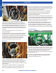
Power Circuit Board (PCB)
The purpose of the Power Circuit Board is to lter out potential electrical noise before it reaches the outdoor unit electronic
circuits. All voltage to operate the outdoor unit circuits must pass through the PCB.
1
6
5
3
4
2