Instructions - Parts Hot Melt Dispense Guns 311209J For dispensing non-flammable hot melt thermoplastic sealants and adhesives. 3500 psi (24.1 MPa, 241 bar) Maximum Working Pressure See page 2 for model information. Important Safety Instructions Read all warnings and instructions in this manual. Save these instructions.
Models Contents Models . . . . . . . . . . . . . . . . . . . . . . . . . . . . . . . . . . . 2 Warnings . . . . . . . . . . . . . . . . . . . . . . . . . . . . . . . . . 3 Installation . . . . . . . . . . . . . . . . . . . . . . . . . . . . . . . . 5 Connect Heated Hose . . . . . . . . . . . . . . . . . . . . . 5 Connect Electrical Cable . . . . . . . . . . . . . . . . . . . 5 Ground the System . . . . . . . . . . . . . . . . . . . . . . . 6 Pressure Relief Procedure . . . . . . . . . . . . . . . . . . .
Warnings Warnings The following warnings are for the setup, use, grounding, maintenance, and repair of this equipment. The exclamation point symbol alerts you to a general warning and the hazard symbol refers to procedure-specific risk. Refer back to these warnings. Additional, product-specific warnings may be found throughout the body of this manual where applicable. WARNING BURN HAZARD Equipment surfaces and fluid that’s heated can become very hot during operation.
Warnings WARNING FIRE AND EXPLOSION HAZARD Flammable fumes, such as solvent and paint fumes, in work area can ignite or explode. To help prevent fire and explosion: • Use equipment only in well ventilated area. • Eliminate all ignition sources; such as pilot lights, cigarettes, portable electric lamps, and plastic drop cloths (potential static arc). • Keep work area free of debris, including solvent, rags and gasoline.
Installation Installation Install gun as follows: Connect Electrical Cable • connect material hose • connect the electrical cable 1. Wrap hose cable around hose one time. Connect electrical cable from hose to gun cable; engage metal clip on top of connector. • make sure the gun is grounded Connect Heated Hose 1. Screw adapter onto gun swivel (A) and tighten securely. Part No. Adapter Hose Size 120264 -120265 -8 -10 -12 -8 JIC x -10 JIC Not required -10 JIC x -12 JIC FIG.
Installation Ground the System The following grounding instructions are minimum requirements for a basic dispensing system. Your system may include other equipment or objects that must be grounded. Check your local electrical code for detailed grounding instructions for your area and type of equipment. Your system must be connected to a true earth ground. • 6 Fluid hoses: use only grounded fluid hoses with a maximum of 25 feet (7.5 m) combined hose length to ensure grounding continuity.
Pressure Relief Procedure Pressure Relief Procedure Trigger Lock Always engage trigger lock when you stop spraying to prevent gun from being triggered accidentally by hand or if dropped or bumped. To engage trigger lock, release trigger and rotate lock downward. See FIG. 6. 1. Fully release gun trigger and engage gun trigger lock. See FIG. 6. Do not try to force trigger valve open with trigger lock engaged. This could result in component failure. 2. Shut off fluid supply pump. 3.
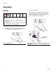
Operation Operation Heatup 3. Activate heat controls. 4. After pump, hose, and gun are up to temperature, release gun trigger retainer (Z) to close valve. Engage gun trigger lock to prevent accidental dispense of high pressure heated fluid. Heated fluid expands, causing a pressure rise in a closed system. • Relieve pressure (page 7) before heating up equipment. • Engage trigger retainer to hold gun open, to prevent excessive pressure buildup. Z 1. Turn ON electrical controls and main air to unit. 2.
Operation Dispensing Shutdown 1. Start pump. Fluid flow rate is controlled at pump. Adjust pump pressure to obtain desired flow rate. Use lowest pressure necessary to dispense fluid. The pressure adjustment depends on hose length, fluid viscosity, and nozzle size. 1. Turn off all heat at controller. 2. Disengage gun trigger lock. 2. Shut off fluid supply pump. 3. Trigger gun to relieve pressure while system is still hot. 4.
Troubleshooting Troubleshooting . Some solutions require disassembling gun. Always relieve system pressure and disconnect electrical cable before performing these procedures. Problem Cause(s) Material leaks from front of gun body Seat or packing is worn Solution(s) Replace seat (6) or packing (47). Obstruction inside gun Remove seat (6). Check and replace if necessary. Worn needle Check and replace needle (4a) if necessary.
Service Service Install New Heater Cartridge(s), RTD Sensor, or Switch After adjusting or servicing gun, ensure that fluid will not trigger on when trigger lock is engaged. If fluid does flow, gun is not assembled correctly or trigger lock is damaged. Reassemble gun or return it to your nearest Graco distributor. Do not use gun until the problem is corrected. 1. If fluid continues to flow after trigger is released: • gun valve may need adjustment, • gun valve may be obstructed or damaged, 1.
Service Inspection Frequency Dispense Valve Inspect dispense valve at every use for leakage or other visible damage. 4. Trigger gun and use a 1/8 in. open-end wrench on flats of needle to turn needle (4a) clockwise one turn as viewed from handle end of gun. 5. Release trigger; a slight free play of the trigger handle should occur. 6. Repeat Step 4 until free play occurs. Heater Every two weeks, check heater for proper resistance.
Notes Notes 311209J 13
Parts Parts Models 249514 and 249512, Hot Melt Guns Model 249512 Only 4j 52 54 51 14 27 50 4d 55 4c 4h 4g 4a 5 25 53 33 14 4f 5 11 4e 24 1 4b 3 23 4 26 27 35 34 16 30 41 21 37 2 31 19 32 47 48 32 46 36 6 22 9 17 10 18 8 7 12 20 13 29 15 TI8058b Detail A TI8059 Orient snap rings as shown. For ease of assembly, install pins and snap rings from top to bottom. Middle snap ring must be installed facing up, then rotated to position shown.
Parts Model 249514 Manual Hot Melt Gun, Bottom Feed, Extrude, No Switch Ref. No. Model 249512 Manual Hot Melt Gun, Bottom Feed, Extrude, with Switch Ref. No. 1 2 3 4◆ 4a 4b 4c* 4d* 4e 4f 4g 4h 4j* 5 6◆ 7 8 9 10 11† 12 13 14 15 16 17 18 19 20 21 22 23 24 25 26 27 28❄ 29 Part No.
Parts Models 249515 and 249513, Hot Melt Guns 15 29 Model 249513 Only 50 55 51 12 54 13 52 14 5 5 20 25 10 53 14 33 27 41 11 24 1 27 35 23 8 32 26 34 4 30 22 3 37 2 32 16 46 31 19 4j 47 36 21 6 4h 4c 4g 4f 4a 17 18 4e 7 4d 9 4b TI8060b Detail A TI8059 Orient snap rings as shown. For ease of assembly, install pins and snap rings from top to bottom. Middle snap ring must be installed facing up, then rotated to position shown.
Parts Model 249515 Manual Hot Melt Gun, Top Feed, Extrude, No Switch Model 249513 Manual Hot Melt Gun, Top Feed, Extrude, with Switch Ref. No. 1 2 3 4◆ 4a 4b 4c* 4d* 4e 4f 4g 4h 4j* 5 Part No.
Parts Models 297274 and 297273, Hot Melt Guns 50 15 4j 29 4d 13 27 4h 4c 12 4a Top feed Model 297273 only 4f 25 52 4g 55 33 4e 24 4b 5 35 23 4 26 34 16 30 37 41 21 2 53 14 1 3 10 51 54 48 46 19 47 32 6 17 9 Bottom feed Model 297274 only 36 32 22 18 8 10 12 7, 56 13 29 20 15 TI8061b Detail A TI8059 Orient snap rings as shown. For ease of assembly, install pins and snap rings from top to bottom.
Parts Model 297274 Manual Hot Melt Gun, Bottom Feed, Swirl, with Switch Model 297273 Manual Hot Melt Gun, Top Feed, Swirl, with Switch Ref. No. Part No.
Accessories Accessories Part No. Description C34137 Fitting insulation, 1/8 in. thick x 2 in. wide. Sold by the foot. Adhesive tape, high temp for securing insulation (C34137), 1 in. x 108 ft. Wrap, velcro, 10 in. x 10 in. Covers electrical connection on heated hose. Strap, velcro. Use two around ends of wrap (198422) for security.
Technical Data Technical Data Maximum operating temperature 400°F (204°C) Maximum fluid working pressure 3500 psi (24.1 MPa, 241 bar) Outlet port size 5/8-18 UNF-2B Inlet port size on gun housing 7/8-14 UNF- 2B Inlet port size on fluid swivel 7/8-14 JIC(m) Voltage 230/240 Vac Wattage 120 W Resistance temperature detector (platinum RTD; 0.00385 ohm/ohm/°C) 108.
Graco Standard Warranty Graco warrants all equipment referenced in this document which is manufactured by Graco and bearing its name to be free from defects in material and workmanship on the date of sale to the original purchaser for use. With the exception of any special, extended, or limited warranty published by Graco, Graco will, for a period of twelve months from the date of sale, repair or replace any part of the equipment determined by Graco to be defective.