SERVICE MANAUL Wall Mounted Type DC Inverter Model No. 1U71SABFRA WARNING This service information is designed for experienced repair technicians only and is not designed for use by the general public. It does not contain warnings or cautions to advise non-technical individuals of potential dangers in attempting to service a product. Products powered by electricity should be serviced or repaired only by experienced professional technicians.
Contents Contents 1. Introduction ............................................................................................1 2. Specifications.........................................................................................7 3. Sensors list ............................................................................................8 4. Piping diagrams .....................................................................................9 5. Operation range ........................................
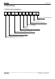
Introduction 1 Introduction 1.
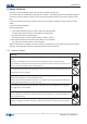
Introduction 1.2 Safety Cautions Be sure to read the following safety cautions before conducting repair work. The caution items are classified into “Warning” and “Caution”. The “Warning” items are especially important since they can lead to death or serious injury if they are not followed closely. The “Caution” items can also lead to serious accidents under some conditions if they are not followed.
Introduction Warning Do not repair the electrical components with wet hands . Working on the equipment with wet hands can cause an electrical shock Do not clean the air conditioner by splashing water. Washing the unit with water can cause an electrical shock. Be sure to provide the grounding when repairing the equipment in a humid or wet place, to avoid electrical shock.
Introduction Warning Be sure to use an exclusive power circuit for the equipment, and follow the technical standards related to the electrical equipment, the internal wiring regulations and the instruction manual for installation when conducting electrical work. Insufficient power circuit capacity and improper electrical work can cause an electrical shock or fire.
Introduction Do not install the equipment in a place where there is a possibility of combustible gas leaks. If a combustible gas leaks and remains around the unit, it can cause a fire. Be sure to install the packing and seal on the installation frame properly. If the packing and seal are not installed properly, water can enter the room and wet the furniture and floor. 1.2.
Introduction Check the grounding, and repair it if the equipment is not properly grounded. Improper grounding can cause an electrical shock. Be sure to measure the insulation resistance after the repair, and make sure that the resistance is 1 M ohm or higher. Faulty insulation can cause an electrical shock. Be sure to check the drainage of the indoor unit after the repair.
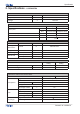
Specification 2. Specifications - 1U53RABFRA NOMINAL DISTRIBUTION SYSTEM VOLTAGE Phase / 1 Frequency Hz 50 Voltage V 220~240 NOMINAL CAPACITY and NOMINAL INPUT cooling W Capacity rated Btu/h Power Consumption(Rated) heating 7100(1900-8400) 7600(2000-10200) 24200(6500-28600) 25900(6800-34800) W 1710 1890 EER/ COP W/W 4.15 4.02 Moisture Removal m³/h 2.
Specification TECHNICAL SPECIFICATIONS-OTHERS Refrigerant circuit Refrigerant type R32 Refrigerant charge Refrigerant control circuit Piping connections (external diameter) 1.45 KG EXV liquid mm gas mm 12.7 drain mm 17 Heat insulation type Both liquid and Gas pipes Max. piping Length m 25 Max.
Pinping diagrams 4.
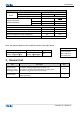
Operation range 5 Operation range 0 -10 -20 32 16 -10 -15 -20 10 Domestic air conditioner
Wiring diagrams 6.
Connector Wiring Diagram PCB (1) CN28 CN25 CN24 CN23 CN22 CN50 CN17 CN47 CN45 CN2 CN15 CN1 CN11 CN36 CN3 CN6 CN7 12 CN10 CN9 Domestic Air Conditioner
Connector Wiring Diagram PCB (2) CN4 CN3 CN1 CN2 CN10 CN9 CN7 CN6 CN5 CN8 CN11 13 Domestic Air Conditioner
Functions and control Wiring diagrams OUTDOOR UNIT WIRING DIAGRAM W B CN24 MODULE COM B CN11 R U P N V W CN5 CN6 CN7 CN8 CN9 BL MOUDLE PCB BL CN23 CN10 CN36 OUTDOOR PCB COMB COMA N R BL(OR W) AC-L OUT AC-L OUT CN10 CN9 AC-N OUT BR(OR B) CN6 BL(OR W) POWER ● BR(OR B) CN7 AC-N OUT ● BL(OR W) AC-N CN1 T25A 250VAC MODULE POWER 1(N) 2(L) FUSE1 TO INDOOR UNIT B CN25 N BR(OR B) AC-L CN2 CAP 3(C) BL CAP 2 OR S(V) P CN28 1 C(W) Y/G Y/G M R(U) COMPRESSOR 0010534175A C
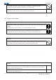
Functions and control 7. Functions and Control 7.1 Main functions and control specification 7.1.1 The operation frequency of outdoor unit and its control 7.1.1.1 The operation frequency control of compressor The operation frequency scope of compressor˖ Mode Minimun operation frequency Maximun operation frequency Heating 20Hz 118Hz Refrigeration 20 Hz 90Hz 7.1.1.
Functions and control 2 Wh_c<32 Max_hz2 74 HZ 3 Wh_c≥40 Max_hz3 90 HZ 4 Wh_c<48 Max_hz4 68 HZ 5 Wh_c≥48 Max_hz5 60 HZ Remarks: the above are not only the maximum frequency limitations of the complete appliance which are affected by the environment, but also the maximum ability limitation of the system.
Functions and control During the compressor is started for 3 seconds, the outdoor fan is controlled the airflow speed according to the temperature conditions of the outdoor environment.
Functions and control 7.1.5 ˖Protection function 7.1.5.
Functions and control 7.1.5.2˖TC high temperature-preventing control of the indoor heating unit Tpg_indoor is the highest value of the effective indoor unit (start it and it is in accord with the running state). The indoor heat exchanger sensor tests the temperature of the indoor heat exchanger.
Functions and control 7.1.5.4˖Antifreezing protection of the indoor heat exchanger When refrigerating/heating, prevent freezing. Tpg_indoor is the minimum value of the effective indoor unit (start it and it is in accord with the running state).
Functions and control 7.1.5.5˖Temperature protection of the outdoor refrigerating coil When the defrosting temperature and the sensor’s temperature are higher than 68ć, the frequency of the compressor decreases 1hz/10seconds. Keep the frequency until it decreases to the lowest frequency. When the temperatures are lower than 68ć and higher than 61ć, keep the frequency of the compressor. When the temperatures are lower than 61ć, relieve the defrosting temperature protection. 7.2 Value of Thermistor 7.2.
Functions and control -26 130.2371 117.4366 105.7989 -1.87 1.70 -25 122.8484 110.9627 100.1367 -1.85 1.69 -24 115.9272 104.8882 94.8149 -1.83 1.67 -23 109.4410 99.1858 89.8106 -1.81 1.66 -22 103.3598 93.8305 85.1031 -1.80 1.64 -21 97.6556 88.7989 80.6728 -1.78 1.63 -20 92.3028 84.0695 76.5017 -1.76 1.62 -19 87.2775 79.6222 72.5729 -1.74 1.60 -18 82.5577 75.4384 68.8710 -1.72 1.59 -17 78.1230 71.5010 65.3815 -1.70 1.57 -16 73.9543 67.7939 62.
Functions and control 19 13.3431 12.8572 12.3778 -0.88 0.87 20 12.7718 12.3223 11.8780 -0.86 0.85 21 12.2280 11.8126 11.4011 -0.83 0.83 22 11.7102 11.3267 10.9459 -0.81 0.80 23 11.2172 10.8634 10.5114 -0.78 0.78 24 10.7475 10.4216 10.0964 -0.75 0.75 25 10.3000 10.0000 9.7000 -0.75 0.75 26 9.8975 9.5974 9.2980 -0.76 0.76 27 9.5129 9.2132 8.9148 -0.80 0.80 28 9.1454 8.8465 8.5496 -0.84 0.83 29 8.7942 8.4964 8.2013 -0.87 0.86 30 8.4583 8.
Functions and control 64 2.5396 2.3611 2.1932 -2.31 2.17 65 2.4591 2.2840 2.1195 -2.36 2.21 66 2.3815 2.2098 2.0486 -2.40 2.25 67 2.3068 2.1383 1.9803 -2.45 2.29 68 2.2347 2.0695 1.9147 -2.49 2.34 69 2.1652 2.0032 1.8516 -2.54 2.38 70 2.0983 1.9393 1.7908 -2.59 2.42 71 2.0337 1.8778 1.7324 -2.63 2.46 72 1.9714 1.8186 1.6761 -2.68 2.50 73 1.9113 1.7614 1.6219 -2.73 2.54 74 1.8533 1.7064 1.5697 -2.78 2.58 75 1.7974 1.6533 1.5194 -2.83 2.
Functions and control 109 0.6877 0.6140 0.5478 -4.63 4.16 110 0.6700 0.5977 0.5328 -4.69 4.21 111 0.6528 0.5820 0.5183 -4.74 4.26 112 0.6361 0.5667 0.5043 -4.80 4.31 113 0.6200 0.5518 0.4907 -4.86 4.36 114 0.6043 0.5374 0.4775 -4.92 4.41 115 0.5891 0.5235 0.4648 -4.98 4.45 116 0.5743 0.5100 0.4524 -5.04 4.50 117 0.5600 0.4968 0.4404 -5.10 4.55 118 0.5460 0.4841 0.4288 -5.16 4.60 119 0.5325 0.4717 0.4175 -5.22 4.65 120 0.5194 0.4597 0.
Functions and control -2 2434.5487 2112.5459 1831.4826 -2.56 2.24 -1 2296.6230 1996.2509 1733.6024 -2.55 2.23 0 2167.2730 1887.0018 1641.4966 -2.53 2.22 1 2045.9191 1784.3336 1554.7931 -2.52 2.21 2 1932.0242 1687.8144 1473.1460 -2.50 2.20 3 1825.0899 1597.0431 1396.2333 -2.48 2.19 4 1724.6540 1511.6468 1323.7551 -2.47 2.17 5 1630.2870 1431.2787 1255.4324 -2.45 2.16 6 1541.5904 1355.6163 1191.0048 -2.43 2.15 7 1458.1938 1284.3593 1130.2298 -2.41 2.
Functions and control 43 239.0983 221.9825 205.9065 -1.71 1.61 44 228.4809 212.4060 197.2844 -1.69 1.59 45 218.3860 203.2887 189.0648 -1.67 1.57 46 208.7855 194.6066 181.2273 -1.65 1.55 47 199.6531 186.3369 173.7524 -1.63 1.54 48 190.9639 178.4584 166.6217 -1.60 1.52 49 182.6945 170.9508 159.8181 -1.58 1.50 50 174.8228 163.7951 153.3249 -1.56 1.48 51 167.3280 156.9733 147.1268 -1.53 1.46 52 160.1904 150.4683 141.2090 -1.51 1.44 53 153.3914 144.
Functions and control 88 38.9643 37.5045 36.0668 -1.11 1.09 89 37.6569 36.2078 34.7831 -1.14 1.13 90 36.3996 34.9622 33.5513 -1.18 1.16 91 35.1903 33.7653 32.3689 -1.22 1.19 92 34.0269 32.6151 31.2338 -1.26 1.23 93 32.9075 31.5096 30.1438 -1.30 1.27 94 31.8302 30.4467 29.0970 -1.33 1.30 95 30.7933 29.4246 28.0915 -1.37 1.34 96 29.7950 28.4417 27.1254 -1.41 1.37 97 28.8337 27.4961 26.1970 -1.45 1.41 98 27.9078 26.5864 25.3048 -1.49 1.
Functions and control 133 9.7563 8.9971 8.2895 -3.00 2.80 134 9.4901 8.7441 8.0495 -3.05 2.84 135 9.2322 8.4993 7.8175 -3.09 2.88 136 8.9824 8.2623 7.5931 -3.14 2.92 137 8.7404 8.0329 7.3760 -3.19 2.96 138 8.5059 7.8108 7.1660 -3.24 3.00 139 8.2787 7.5958 6.9629 -3.29 3.04 140 8.0584 7.3875 6.7664 -3.33 3.
Dimensinal drawings 8.Dimensional drawings 1018 920 762 385 3/4 385 12.7 920 9.
Connector Wiring Diagram 1 .Service Diagnosis 1 .1.1 Caution for Diagnosis The operation lamp flashes when any of the following errors is detected. 1.When a protection device of the indoor or outdoor unit is activated or when the thermistor malfunctions, disabling equipment operation. 2.When a signal transmission error occurs between the indoor and outdoor units.In either case, conduct the diagnostic procedure described in the following pages. 1 .1.
Connector Wiring Diagram 1 .
Seivice diagnosis 10.3.2 EEPROM abnormal 10 Indoor Display Outdoor display E4: indoor EEPROM error F12: Outdoor EEPROM error; Outdoor LED1 flash 1 times Indoor AC fan motor malfunction 10.3.
Seivice diagnosis 10.3.
Seivice diagnosis 10.3.
Seivice diagnosis 10.3.
Seivice diagnosis 10.3.
Seivice diagnosis 10.3.
Seivice diagnosis 10.3.
Seivice diagnosis 10.3.
Seivice diagnosis 41 Domestic air conditioner
Seivice diagnosis 42 Domestic air conditioner
Seivice diagnosis 43 Domestic air conditioner
Seivice diagnosis 10.3.11 Compressor loss of synchronism detection Outdoor Display 10.3.
Performance and curves diagrams 11.Performence and curves diagrams 11.1 Cooling capacity-temperature curves performance curves cooling value-temerature table indoor temp. outdoor temp DB/WB 10℃ 15℃ 20℃ 25℃ 30℃ 35℃ 38℃ 40℃ 43℃ 21/15℃ 6272 6124.8 5950 5600 5460 5152 4900 4606 4360 24/16℃ 6720 6510 6104 6020 5776.4 5390 5180 4956 4610 27/19℃ 6804 6720 6454 6370 6098.4 5740 5460 5180 4830 30/22℃ 7084 7000 6762 6552 6300 5950 5740 5524.
Performance and curves diagrams 11.2 Cooling power consumption value- temperature curves performance curves power consumption temp.table indoor temp. outdoor temp.
Performance and curves diagrams 11.3 Cooling discharge pressure curves performance curves cooling discharge pressure.table outdoor temp. (humidity 46%) indoor temp. DB/WB 21/15 27/19 35/24 10 1899 2010 2107 15 1949 2037 2141 20 1976 2064 2178 25 2079 2144 2287 30 2211 2385 2478 35 2429 2546 2674 38 2615 2734 2901 40 2940 3082 3234 43 3359 3484 3650 cooling discharge pressure and temp.
Performance and curves diagrams 11.4 Cooling suction pressure curves performance curves cooling suction pressure.table outdoor temp. (humidity 46%) DB/WB indoor temp.
Performance and curves diagrams 11.5 Heating capacity-temperature curves performance curves heating capacity and indoor/outdoor temp.table outdoor temp. indoor temp.(humidity 46%) DB/WB 10℃ 20℃ 27℃ -15℃ 5194 4686 4190 -10℃ 6526 5877 5158 -7/-8℃ 7920 7181 6289 2/1℃ 9780 8722 7663 7/6℃ 9629 8477 7481 12/11℃ 9417 8268 6892 18/16℃ 7209 6537 5727 24/20℃ 5941 5252 4698 10000 heating capacity and indoor/outdoor temp.
Performance and curves diagrams 11.6 Heating power consumption value- temperature curves performance curves power consumption value-temp.table indoor temp.(humidity 46%) outdoor temp.
Performance and curves diagrams 11.7 Heating discharge pressure curves performance curves heating discharge pressure.table indoor temp. outdoor temp DB/WB 10 20 27 -15 2644 2764 2867 -10 2789 2980 3073 -7/-8 3259 3411 3563 2/1 3461 3698 3883 7/6 3409 3590 3672 12/11 3346 3482 3606 18/16 3098 3273 3351 24/20 2638 2782 2923 heating discharge pressure and temp.
Performance and curves diagrams 11.8 Heating suction pressure curves performance curves heating suction pressure.table indoor temp. outdoor temp DB/WB 10 20 27 -15 345 385 405 -10 398 428 447 -7/-8 492 532 551 2/1 611 651 670 7/6 744 784 803 12/11 844 884 904 18/16 1011 1051 1071 24/20 1197 1237 1257 heating suction pressure and temp.
Circuit diagrams 12 Circuit diagrams 12.
Circuit diagrams 54 Domestic air conditioner
D C B A B3B-XH 5V 3 2 1 CN10 B3B-XH 3 2 1 CN11 8 6 5 R224 4.7K 4.7K R011 15V C018 103 1 E501 100U/25V E504 100U/25V COM R211 1K 3 2 3 2 C011 104 R016 1K C017 223 330 R014 R214 47 10K 6.2K R204 PC817A C016 472 PC817A 1 2 3 4 R203 1K 3 PC1 4 1K R201 1K 10K R210 R209 1 PC2 2 5V 7 7 GND GND GND GND 104 3 C204 330 2 VCC GND SCL SDA 8 7 6 5 5V 5V IC5A 预留 R018 R019 4.
Circuit diagrams Sincere Forever Haier Group Haier Industrial Park, No.1, Haier Road 266101, Qingdao, China_ Http //www.haier.
Wall Mounted Type ON/OFF-Series SERIES:70 PLATFORM WARNING This service information is designed for experienced repair technicians only and is not designed for use by the general public. It does not contain warnings or cautions to advise non-technical individuals of potential dangers in attempting to service a product. Products powered by electricity should be serviced or repaired only by experienced professional technicians.
Removal of procedure 1.Removal of Outdoor panel Procedure Warning Be sure to wait 10 minutes or more after turning off all power supplies before disassembling work Step Procedure Points 1.Remove the panels 1 Loosen the 8 screws and lift the top panel.
Step 2 Removal of procedure Points Procedure Loosen the screws of the panel, pull and remove the front panel.
Removal of procedure 2.Removal of Electrical Box Procedure Warning Be sure to wait 10 minutes or more after turning off all power supplies before disassembling work Step 1 Procedure Points Remove the fixing screws, Than lift the electrical box.
Removal of procedure 3.Removal of Fan and Fan Motor Procedure Warning Be sure to wait 10 minutes or more after turning off all power supplies before disassembling work Step 1 Procedure Points Put the head wire through the back of the motor when assembling.(so as not to be entangled with the propeller fan) Loosen the fixing screw and remove the fan.
Step 2 Removal of procedure Points Procedure Loosen the fixing screws and remove the fan motor.
Removal of procedure 4.Removal of fan motor bracket and partition Procedure Warning Be sure to wait 10 minutes or more after turning off all power supplies before disassembling work Step 1 Procedure Points Loosen the fixing screws and remove the fan motor bracket.
Step 2 Removal of procedure Points Procedure Loosen the fixing screws, the partition plate has a hook on the lower side, than lift and pull the proof plate. When assembling, fit the lower hook into the bottom frame.
Removal of procedure 5.Removal of compressor and heat exchanger Procedure Warning Be sure to wait 10 minutes or more after turning off all power supplies before disassembling work Step 1 Procedure Points Cut down the concenting pipe and put out the compressor and remove the valve bracket.
Step 2 Removal of procedure Points Procedure Loosen the marked fixing screws and remove the heat exchanger.
Read the precautions in this manual carefully before operating the unit. This appliance is filled with R32. Keep this manual where the user can easily nd it. WARNING: · · ·· · · · Do not use means to accelerate the defrosting process or to clean, other than those recommended by the manufacturer. The appliance must be stored in a room without continuously operating ignition sources (for example: open flames, an operating gas appliance or an operating electric heater). Do not pierce or burn.
Installation Manual of Room Air Conditioner Preparation Selection of Installation Place Necessary Tools for Installation Indoor Unit Torque wrench (17mm,22mm,26mm) Pipe cutter Flaring tool Knife Measuring tape Reamer Driver Nipper Hacksaw Hole core drill Spanner(17,19 and 26mm) Gas leakage detector or soap-and-water solution Place, robust not causing vibration, where the body can be supported suf ciently.
320 256 500 140 140 Floor fixing dimensions of the outdoor unit (Unit:mm) 1U09BYFSRA 590 114.2 114.2 Floor fixing dimensions of the outdoor unit (Unit:mm) Refer to the previous article, “ When the mounting plate is rst xed “, for the position of wall hole. 1U09JACFRA 1U12JACFRA 1U26JACFRA 1U35JACFRA 1U12BYFSRA When the mounting plate is xed side bar and lintel Fix to side bar and lintel a mounting bar, Which is separately sold, and then fasten the plate to the xed mounting bar.
4 Outdoor unit Connecting the indoor/outdoor Electric Cable Removing the wiring cover Installation of Outdoor Unit 1 Drawing for the installation of indoor and outdoor units Install according to Connection of pipes 2 Remove terminal cover at right bottom corner of indoor unit, then take off wiring cover by removing its screws. To bend a pipe, give the roundness as large as possible not to crush the pipe , and the bending radius should be 30 to 40 mm or longer.
5. No gas leakage? In case of gas leakage, tighten parts of pipe connection. If leakage stops, then proceed 6. steps On Drainage Please install the drain hose so as to be downward slope without fail. Please don’t do the drainage as shown below. If it does not stop gas leakage, discharge whole refrigerants from the service port. After aring work again and vacuumize, ll up prescribed refrigerant from the gas cylinder. 6. Detach the charge hose from the service port, open 2-way valve and 3-way.