Ductless Split Heat Pump Installation Manual Indoor AM24LP2VHA AM36LP2VHA AM48LP2VHA AL24LP2VHA AL36LP2VHA AL48LP2VHA AW24LP2VHA AW36LP2VHA Outdoor 1U24LP2VHA 1U36LP2VHA 1U48LP2VHA Table of Contents Nomenclature ............................................................................................................................... 2 ................................................................................................................... 3 Safety ........................................
Nomenclature ENGLISH Nomenclature 1 U 24 18 LP ES 2 V H HA A Unit Type A = Indoor Unit 1 = Single Zone Outdoor 2 = Two Zone Outdoor 3 = Three Zone Outdoor 4 = Four Zone Outdoor Product Revision System Type H = Heat Pump C = Cool Only Unit Type U = Outdoor B = Casse e Type Indoor D = High ESP Duct Type Indoor M=High Static Duct Type Indoor W = Wall Mount Type Indoor L = Large Cassette Type Indoor Nominal Capacity In Btu/hr (x 1000) PAGE 2 Compressor Speed V = Variable Speed Voltage 1 = 115V Product
Operating Range Power Supply Outdoor Unit System Outdoor Indoor Cooling °F(°C) Heating °F(°C) AW24LP AW36LP AM24LP AM36LP AM48LP AL24LP AL36LP AL48LP 1U24LP2VH 1U36LP2VH 1U24LP2VH 1U36LP2VH 1U48LP2VH 1U24LP2VH 1U36LP2VH 1U48LP2VH AW24LP2VH AW36LP2VH AM24LP2VH AM36LP2VH AM48LP2VH AL24LP2VH AL36LP2VH AL48LP2VH 0~115 0~115 0~115 0~115 0~115 0~115 0~115 0~115 (-18~46) (-18~46) (-18~46) (-18~46) (-18~46) (-18~46) (-18~46) (-18~46) -4~75 -4~75 -4~75 -4~75 -4~75 -4~75 -4~75 -4~75 (-20~24) (-20~24) (-20~24) (-20
ENGLISH SAFETY OVERVIEW Read These Safety Precautions Be sure to read the safety precautions before conducting work. The items are classified into “Warning” and “Caution.” The “Warning" items are especially important since they can lead to death or serious injury if not followed closely. Under certain conditions, the "Caution" items can also lead to accident or injury if they are not followed. Therefore, be sure to observe all safety precautions listed here.
SAFETY OVERVIEW Be sure to use the specified cable to connect between the indoor and outdoor units. Make the connections securely and route the cable properly so that there is no force pulling the cable at the connection terminals. When connecting the cable between the indoor and outdoor units make sure that the terminal cover does not lift off or dismount because of the cable.
[This page intentionally left blank.
Section A - Outdoor Unit Installation Step 1 - Installation of the Outdoor Unit ENGLISH Attaching Drain Elbow to Outdoor Unit (Heat Pump models only) 1.1 Step - 1.1 If attaching the supplied drain elbow to the outdoor unit, do so prior to attaching the refrigerant lines and wiring. Extension piping to attach to this fitting is field supplied. Step 1.1 Step1.2 Step 1.3 Step 1.4 Electrical Connections for the Outdoor Unit 1.2 Step - 1.
ENGLISH 2.3 Step - 2.3 Two wrenches are required to join the flare connections, one standard wrench, and one torque wrench. See Table 1 for the specific torque per piping diameter. Half union Flare nut Forced fastening without careful centering may damage the threads and cause a leakage of gas. Pipe Diameter(ǿ) Fastening torque Liquid side6.35mm(1/4") 18N.m/13.3Ft.lbs Step 2.3 Liquid/Gas side9.52mm(3/8") 42 N.m/30.1Ft.lbs Spanner Torque wrench Gas side 12.7mm(1/2") 55N.m/40.6Ft.
3.3 Step - 3.3 3.4 Step - 3.4A & 3.4B Step 3.3 Step 3.4A Step 3.4B Step 3.5A Step 3.5B Step 3.6 ENGLISH Remove the adapter and hose connection from the suction line port, and replace the cap. Hoses should not be removed and service valves should not be opened until any additional refrigerant needed for a refrigerant line longer than 25 ft. has first been added. Remove the cap from the liquid line valve. Using the hex wrench, open the valve, then replace and tighten the cap. 3.5 Step - 3.5A & 3.
ENGLISH Step 4 - Charging See Steps 5.2 - 5.5 for evacuating the system prior to charging. The standard lineset length is 25ft. If the installation length is different, adjust the refrigerant charge by .5 oz / ft. for the 24K, 36K and 48K model. (Step 4 Illustration 4) This product contains fluorinated greenhouse gases covered by the Kyoto Protocol. Do not vent into the atmosphere.
Section 5 - Explaining Operation to the End User Section 6 - Seacoast Application ENGLISH • Using the OPERATING INSTRUCTIONS, explain to the user how to use the air conditioner (the remote controller, removing the air filters, placing or removing the remote controller from the remote controller holder, cleaning methods, precautions for operation, etc.) • Recommend that the user read the OPERATING INSTRUCTIONS carefully.
[This page intentionally left blank.
Section B - Indoor Unit Installation - Wall Mount • • • • • • • • • • • • • • • • • • • • • • Required Tools for Installation Procedure for Selecting the Location Drill Wire Snipper Hole Saw 2 3/4” Vacuum pump Soap-and-water solution or gas leakage detector Torque wrench 17mm, 22mm, 26mm Tubing cutter Flaring tool Razor knife Measuring tape Level Micron gauge Nitrogen Mini-Split AD-87 Adapter (1/4” to 5/16”) A - Non-adhesive Tape B - Adhesive Tape C - Saddle (L.S.
Step 2 - Installation of Wall Mount Type Indoor Unit ENGLISH Attaching the Mounting Plate to the Wall 2.1 Step 2.1 Using a stud sensor, locate and mark the stud positions in the wall where the indoor unit is to be mounted. 2.2 Step 2.2 Place the mounting plate on the wall in the desired location taking into account the minimum clearances necessary for proper operation. Step 2.1 Step 2.2 Step 2.3 Step 2.4 Step 2.5A Step 2.5B Step 2.6 Step 2.7 Step 2.8A Step 2.
Mounting the Indoor Unit Onto the Wall Plate 2.9 Step 2.9 ENGLISH With the top of the indoor unit closer to the wall, hang the indoor unit on the upper hooks of the mounting plate. Slide the unit slightly side to side to verify proper placement of the indoor unit on the mounting plate. Rotate the lower portion of the indoor unit to the mounting plate, and lower the unit onto the lower hooks of the mounting plate. (Illustration 2) Verify the unit is secure. 2.10 Step 2.10 Step 2.9 Step - 2.
[This page intentionally left blank.
Section C - Indoor Unit Installation - Cassette Introduction - Overview The Cassette Indoor Air Handler ships consisting of a cassette assembly and operational louver. The Cassette Indoor Unit is operated via a factory supplied remote control. Wired controller is optional.
ENGLISH Introduction - Overview Fresh Air Intake Option Electrical Power The cassette has a marked area to cut out if outside air is desired. The piping connection should be made with a 4 inch Follow all local codes and regulations when installing electrical wiring. entry into the cassette. Route required electrical power to area where cassette is to be located. Maintain at least a 10 foot separation between TV and Radio wiring and the power to the indoor unit.
Step 1 - Preparation Required Tools for Installation • • • • • • • • • • • • • • • • • Drill Wire Snipper Hole Saw 2 3/4” Vacuum pump Soap-and-water solution or gas leakage detector Torque wrench 17mm, 22mm, 26mm Tubing cutter Flaring tool Razor knife Measuring tape Level Micron gauge Nitrogen Mini-Split AD-87 Adapter (1/4” to 5/16”) A - Non-adhesive Tape B - Adhesive Tape C - Saddle (L.S.
Step 2 - Installation of the Cassette Unit ENGLISH Step By Step Guide To Cassette Installation 2.1 Step 2.1 Step 2.1 Use cardboard template to locate center point of cassette for mounting. Use a plumb bob and string to position cassette by referencing center hole of template. Mark the mounting positions of the threaded rods using the guides on the cardboard template. 2.2 Step 2.2 Install threaded rods to structure using appropriate fasteners. 2.3 Step 2.
Step 2 - Installation of the Cassette Unit Step 2.5A Step 2.8A ENGLISH Step 2.5B Step 2.8B Step 2.6 Step 2.8C Step 2.7 Step 2.
Step 3 - Electrical Connections ENGLISH Electrical Connections Indoor and Outdoor Units 14 AWG Stranded Wire Only. (Central Controller Not Used) Maintain 10 feet of separation between TV and any Radio wiring. Outdoor unit 1(N) 2 (L) 3 (C) Indoor unit 3wire 1 4AWG Control Wiring 1( N ) 2 (L) 3 (C ) Power Wiring Outdoor unit Note: Cassette unit ships with YR-HBS01 remote controller. See Section F for more information.
Section D - Indoor Unit Installation - High ESP Duct High ESP Duct Product Information The High ESP Duct Indoor Air Handler ships consisting of a single assembly. The High ESP Duct indoor unit is operated via a factory supplied wired remote control. High ESP YR-E17 Wired Controller See Section E for more information ENGLISH Introduction - Overview g that are located at all four corners of the High ESP Duct assembly.
ENGLISH Introduction - Overview Condensate Handling Electrical Power The High ESP Duct unit has a built-in condensate pump and water level safety switch. There are also two optional ports for gravity drainage. The condensate pump is rated to lift water up to 24” from the point of discharge on the High ESP Duct unit. The High ESP Duct unit comes with a grey connection hose with clamp. This hose is connected to the High ESP Duct unit condensate discharge hose port.
Step 1 - Preparation Required Tools for Installation • • • • • • • • • • • • • • • • • Drill Wire Snipper Hole Saw 2 3/4” Vacuum pump Soap-and-water solution or gas leakage detector Torque wrench 17mm, 22mm, 26mm Tubing cutter Flaring tool Razor knife Measuring tape Level Micron gauge Nitrogen Mini-Split AD-87 Adapter (1/4” to 5/16”) A - Non-adhesive Tape B - Adhesive Tape C - Saddle (L.S.
ENGLISH Step 2 - Installation of the High ESP Duct Unit Step By Step Guide To High ESP Duct Unit Installation 2.1 Step 2.1 Step 2.1 Determine and mark the position of where the High ESP Duct unit is to be installed. Install the hardware necessary to mount the threaded rods. Always select a location strong enough to support the indoor High ESP Duct unit. 2.2 Step 2.2 Install the threaded rods to the hardware attached to the structure. 2.3 Step 2.
Step 2 - Installation of the High ESP Duct Unit Step 2.7A Step 2.5A Step 2.7B Re-install electrical box cover ENGLISH Step 2.5 Step 2.6 Step 2.8 Rear side air inlet Diffuser Return Duct Bottom side air inlet Step 2.
Step 3 - Electrical Connections ENGLISH Electrical Connections Indoor and Outdoor Units 14 AWG Stranded Wire Only. (Central Controller Not Used) Maintain 10 feet of separation between TV and any Radio wiring. Outdoor unit 1(N) 2 (L) 3 (C) Indoor unit 3wire 1 4AWG Control Wiring 1( N ) 2 (L) 3 (C ) Power Wiring Note: High ESP Duct unit ships with YR-E17 wired controller. See Section E for more information. See Step 3.2 of the outdoor unit installation section for how to pull a vacuum.
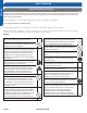
Section E - Wired Controller YR-E17 ENGLISH WIRED CONTROL PANEL FUNCTIONS Features and Interface Clock; Parameter setting/Inquiry; Malfunction display Timer ON/OFF; Sleep function; Parameter setting/Inquiry; Malfunction display ROOM/SET temp. and humidity display, each step is 0.5°C (1°F). For example, if the temp is 25°C (77°F), it will display 25.°C (77°F). Humidity display function is reserved. Energy Saving function. This icon will be displayed only when energy saving function is set.
A TYPE 1, FOR AL24/36/42/48LP2VHA, AM24LP2VHA Indoor 1 Wire controller port Indoor 15 Indoor N Indoor 2 Wire controller port Wire controller port Indoor16 (master unit) Wire controller port The communication wiring is 189ft (4.
WIRED CONTROLLER INSTALLATION Wired Controller Wiring Instructions ENGLISH Dimensions Unit: inch (mm) Dip Switch Dip Switch SW1-1 SW1-2 SW1-3 SW1-4 SW1-5 SW1-6 SW1-7 SW1-8 ON/OFF ON OFF ON OFF ON OFF ON OFF ON OFF ON OFF ON OFF ON OFF Function Set as the slave controller Set as the master controller Ambient temp. display available Ambient temp. display unavailable Display ambient temp. from PCB of indoor Display ambient Temp.
WIRED CONTROLLER OPERATION ENGLISH Settings & Functions Switching between Fahrenheit & Celsius Initialization The wired controller will momentarily display all display icons upon powering up or when resetting the system. To switch from Celsius to Fahrenheit, select the mode you wish to operate (COOL, HEAT, DRY, INTELLIGENT/AUTO). Press and hold the p key to reach 30 °C then continue holding the p key for 15 seconds until the display reads 86 °F. Use the pq keys to adjust to desired temperature.
WIRED CONTROLLER OPERATION Settings & Functions NOTE: This function requires the ON/OFF key LED to be turned ON and the screen backlight to be illuminated. Press the SET key. The swing louver function icon will be displayed. Press the pq keys to advance through the functions to select ECO function. (The icon will be flashing) Press the SET key to confirm the setting. The ECO icon will remain on. NOTE: The display backlight must be illuminated before proceeding.
WIRED CONTROLLER OPERATION ENGLISH Settings & Functions Left/Right/Up/Down Swing Forced Cooling/Heating The swing function determines air circulation. Note: This function requires the ON/OFF key LED to be turned OFF and the screen backlight to be illuminated. 1. Press SET key to access Swing function circulation. 2. Use pqkeys to select desired swing function. Forced Cooling When the system is turned off in cooling mode, press and hold the ON/OFF key for 10 seconds.
WIRED CONTROLLER OPERATION Settings & Functions Other Functions NOTE: This function requires the ON/OFF key LED to be turned ON and the screen backlight to be illuminated. Note: These functions require the ON/OFF key LED to be turned OFF and the screen backlight to be illuminated. Press the SET key. The swing louver function icon will be displayed. Press the pq keys to advance through the functions to select the SLEEP function. The Sleep and Sleep “off” time icons will be displayed.
[This page intentionally left blank.
Section F - Wireless Remote Controller Functions Running the unit in QUIET mode for a long period of time may cause the room temperature to not reach the set temperature. If this occurs, cancel QUIET mode and set the fan speed to a higher setting. ENGLISH Note: TURBO/QUIET modes are only available when the unit is under cooling or heating mode (not for auto or fan mode). 3 COOL Button In COOL mode, the unit operates in cooling.
WIRELESS REMOTE CONTROLLER OPERATION ENGLISH 9 Louver SWING Button - Vertical Air Flow Direction Adjustment Press the SWING UP/DOWN button to choose the position of the vertical airflow louvers. The remote control display changes as follows: BLANK 0.5h Status display of air flow COOL/DRY: 0.5h TIMER ON-OFF 0.5h TIMER OFF-ON Cancel TIMER ON setting: With a TIMER ON set, press the CONFIRM/CANCEL button once to cancel the TIMER ON.
WIRELESS REMOTE CONTROLLER OPERATION According to the Time setting sequence of TIMER ON or TIMER OFF, either Start-Stop or Stop-Start can be achieved. 13 SLEEP Button Sleep mode Press the Extra Function button to enter additional options, cycle the button to display the icon will flash. Press the Confirm/Cancel enter the sleep function. icon, the button to Sleep Operation Mode 1.
ENGLISH WIRELESS REMOTE CONTROLLER OPERATION G) Fahrenheit/Celsius mode shift on unit and remote To switch between Fahrenheit and Celsius press the EXTRA FUNCTION button until either Celsius or Fahrenheit button to is displayed. Press the CONFIRM/CANCEL apply the change. H) 50°F low temperature heating - Feature not available on this series. I) Electrical heating - Feature not available on this series. 15 HEALTH Button Feature not available on this series.
[This page intentionally left blank.
www.Haier.com Model #: 1U24LP2VHA, 1U36LP2VHA, 1U48LP2VHA, AM24LP2VHA, AM36LP2VHA, AM48LP2VHA, AL24LP2VHA, AL36LP2VHA, AL48LP2VHA,AW24LP2VHA,AW36LP2VHA Issued Date: Jan 2017 Haier America, Wayne, NJ 07470 ©2017 Haier America Trading, LLC.