
Installation Manual


INSTALLATION
PAGE 14
ENGLISHSECTION B
2.1
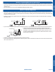
Step 2.1
Using a stud sensor, locate and mark the stud positions in the
wall where the indoor unit is to be mounted.
2.2
Step 2.2
Place the mounting plate on the wall in the desired location
taking into account the minimum clearances necessary for
proper operation.
Using a level, verify the mounting plate is horizontal and mark
the screw locations.
2.3
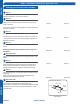
Step 2.3
Screw the mounting plate to the wall.
The piping for the indoor unit may be routed to the unit from
one of several directions. Left, Left Rear, Right, Right Rear, or
Below (Illustration 1).
2.4
Step 2.4
Knockouts are provided on the case for Left, Right, and Right
Below.
Drilling the hole through the wall for left rear or right rear
installation
2.5
Step 2.5A & 2.5B
Measure and mark the location where the piping hole is to be
drilled.
2.6
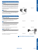
Step 2.6
Drill the piping hole using a hole saw of the correct diameter.
Angle the drill with a downward pitch to the outside wall so
that the outside hole will be ¼” lower than the inside hole,
giving the hole the proper angle for condensate drainage.
2.7
Step 2.7
Install the piping hole cover ange at the hole opening on the
inside wall.
NOTE: The cover ange may require modication to t
properly behind the wall unit housing.
2.8
Step 2.8A & 2.8B
Bundle the refrigerant piping, drain piping and wiring with
tape and pass the bundle through the piping hole.
NOTE: When bundling the power cable, leave sucient length
available in the indoor unit to make the connections to the
terminal block.
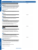
Step 2.1
Step 2.3
Step 2.2
Step 2.4
Step 2.5B
Step 2.7
Step 2.8B
Step 2.5A
Step 2.6
Step 2.8A
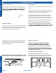
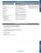
Illustration 1
Piping Exit Options
Rear left
Left
Rear
right
Right
Below
Step 2 - Installation of Wall Mount Type Indoor Unit
Attaching the Mounting Plate to the Wall