
Installation Manual


INSTALLATION
PAGE 15
ENGLISH SECTION B
Illustration 2
Illustration 3
2.9
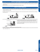
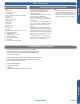
Step 2.9
With the top of the indoor unit closer to the wall, hang the
indoor unit on the upper hooks of the mounting plate. Slide
the unit slightly side to side to verify proper placement of the
indoor unit on the mounting plate. Rotate the lower portion
of the indoor unit to the mounting plate, and lower the unit
onto the lower hooks of the mounting plate. (Illustration 2)
Verify the unit is secure.
2.10
Step - 2.10
Slightly raise the entire unit vertically, pull the lower portion
of the unit o the lower hooks of the mounting plate and
away from the wall, then lift the upper portion of the unit o
the upper hooks of the wall plate.
Step 2.9
Step 2.10
Step 2.11A
Step 2.12
Step 2.13B
Step 2.11B
Step 2.13A
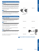
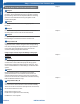
mounting plate
Outdoor unit
3
2
Power
Wiring
1
)
(
N
)
(L
)
(
C
3
2
1
)
(
N
)
(
L
)
(
C
Indoor unit
3wire 14AWG
Control Wiring
Outdoor unit
3
2
Power
Wiring
1
)
(
N
)
(L
)
(
C
2
1
)
(
N
)
(
L
Indoor uni
t
3wire 14AWG
Control Wiring
Mounting the Indoor Unit Onto the Wall Plate
Electrical Connections for the Indoor Unit
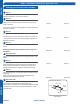
2.11
Step - 2.11A & 2.11B
To make the electrical connections for the indoor unit, two
cover plates must be removed. Raise the front cover to
access the screws to remove these covers.
2.13
Step - 2.13
Access the four conductor cable through the cover plate
opening and make the wiring connections noting the wire
color used on each terminal. The color of each wire must
match the same positions on the terminal block of the
outdoor unit. (Illustration 3)
Failure to wire the system correctly may lead to improper
operation or component damage.
2.14
Step - 2.14A & 2.14B
After the terminal block wiring is completed, replace both
cover plates.
Note: Wall mount unit ships with HG remote controller. See
Section F for more information.
Indoor Wall Unit Installation Complete