INSTRUCTION MANUAL FIRST MADE FOR SAP-KC18AM, KC18AGH MATERIAL OR MODEL *PAPER-JO DIMENSION OR MAKER WOODFREE 80gm COLOR BLACK Print NOTE A4 SIZE APPROVALS N.Yamazaki 2009/Nov /26 CHECK Tai C.S 2009/Nov /25 DESIGN Tai C S 2009/Sep/08 Tai C.S A 1 22 Dec 09 APPROVALS DRAWN DATE P.g 33, additional Flare Nut REVISIONS PART CODE REMARKS: SAMS ONLY 85S-6-4181-002-00-0 PART NAME EXPLANATORY BOOKLET 1 R.
INSTRUCTION MANUAL Split System Air Conditioner INDOOOR UNIT OUTDOOR UNIT COOL / DRY MODEL SAP-K18AM / AMS SAP-C18AM / AMS HEAT PUMP MODEL SAP-K18AGH SAP-C18AGH SAP-K12A H P- 1 A H Save These Instructions! Pub. OI-85264181002000 © SANYO 2010 SANYO Electric Co., Ltd.
Instruction Manual Instruction Manual Contents Page Operation and Maintenance 1. 2. 3. 4. 5. 6. Notices for operation ................... .......................................... Notices for user ................................................................ Names and functions of each part .................................... Operation of wireless remote control unit .......................... Clean and care ................................................................. Troubleshooting ..........
Operation and Maintenance 1. NOTICES FOR OPERATION Each unit must be properly grounded with a ground (or earth) wire or through the supply wiring. Don't attempt to repair the air conditioner by yourself. Select the most appropriate temperature. Keep room cooler than outside about 5 oC. If not, please ask the qualified personnel to install. Furthermore, do not connect each wire to the gas pipe,water pipe, drainage pipe or any other improper places.
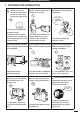
Operation and Maintenance 1. NOTICES FOR OPERATION Do not use the air conditioner for other purposes,such as drying clothes, preserving foods, etc. Do not place a space heater near the air conditioner. CO toxicosis may occur as a result of imcomplete burning. Do not insert your hands or stick into the air intake or outlet vents. Do not blow the wind to animals and plants directly. It can cause a bad influence to them. Splashing water on the air conditioner can cause electric shock or malfunction.
Operation and Maintenance 2. NOTICES FOR USER 2.1 Working Principle and Special Functions for Cooling Principle: Air conditioner absorbs heat in the room and transmit to outdoor and discharged, so that indoor ambient temperature decreased. It's cooling capacity will decrease by the increase of outdoor ambient temperature.
Operation and Maintenance 2. NOTICES FOR USER 2.3 Working Temperature Range COOLING HEATING Temperature Indoor air temperature Outdoor air temperature Max. 32 °C DB / 23 °C DB 43 °C DB / 26 °C DB Min. 21 °C DB / 15 °C DB 21 °C DB / --- Max. 27 °C DB / --- 24 °C DB / 18 °C DB Min. 20 °C DB / --- -5 °C DB / -6 °C DB The operating temperature range (outdoor temperature) for cooling unit is 21 °C ~ 43 °C; for cooling and heating unit is -5 °C ~ 43 °C. 2.
Operation and Maintenance 3. NAMES AND FUCTIONS OF EACH PART Indoor Unit Air intake (1) (3) *(5) x 2pcs (6) (4) Back side of part (4) (10) (9) Air outlet (2) (7) (8) The pattern in displayer: :Cool :Dry :Fan :Heat :Run Wireless remote control S/n (1) (2) (3) (4) (5) :Set temp.
Operation and Maintenance 4. OPERATION OF WIRELESS REMOTE CONTROL UNIT 4.1 Remote Control Unit (Display) Displayed when transmitting data Displayed when setting temperature Displayed the clock Displayed when setting timer Symbols (1) Operation mode AUTO .......................... (4) Timer 24-hour ON Timer ......... COOL .......................... 24hour OFF Timer ......... DRY.............................. (5) Sleep .............................. FAN .............................
Operation and Maintenance 4. OPERATION OF WIRELESS REMOTE CONTROL UNIT 4.2 Remote Control Unit (Functions) Signal Transmitter Display ON/OFF operation button MODE operation button EG TEMP.
Operation and Maintenance 4. OPERATION OF WIRELESS REMOTE CONTROL UNIT 4.2 Remote Control Unit Functions (Continued) FAN SPEED selector button AUTO : : : : The air conditioner automatically decides the fan speeds. Low fan speed. Medium fan speed. High fan speed. AUTO TEMP button NOTE BLOW button Press to begin or stop indoor fan from blowing indoor components to dry. This function applicable to “COOL” & “DRY” mode only.
Operation and Maintenance 4. OPERATION OF WIRELESS REMOTE CONTROL UNIT 4.3 Using the General Operation STEP 1 STEP 2 STEP 3 STEP 4 STEP 5 NOTE Press the setting buttons as described below and change the settings as desired. STEP 1 To start the air conditioner, press the ON/OFF operation button. STEP 2 Press the MODE selector button and select the desired mode.
Operation and Maintenance 4. OPERATION OF WIRELESS REMOTE CONTROL UNIT 4.4 Using the 24-Hour “ON” or “OFF” Timer 4.4.1 TIMER ON mode (Example) After the length of time set for TIMER ON elapses, the unit begins operating. The display depicted at left indicates that the air conditioner will begin operating in 10 hours. Setting procedure: STEP 1 Press the “ON/OFF” button and press “MODE” button to set the desired operation mode. (See “Operation with the Remote Control Unit”, Pg10).
Operation and Maintenance 4. OPERATION OF WIRELESS REMOTE CONTROL UNIT 4.5 Using the SLEEP Operation SLEEP Mode is used for saving energy. Press the SLEEP button while operation. The mark appears in the display. To release the SLEEP function, press the SLEEP button again. 4.5.
Operation and Maintenance 4. OPERATION OF WIRELESS REMOTE CONTROL UNIT 4.6 Using of the “SPECIAL” Features & Remarks “DRY” Operation How it works? “AUTO” Operation How it works? “BLOW” Operation How it works? “TURBO” Operation How it works? “LIGHT” Operation How it works? • During DRY operation, the fan speed is automatically set to LOW. • If the room temp. is 2 °C higher than the Set Temperature, the unit will run in COOL mode. • Once the room temp.
Operation and Maintenance 4. OPERATION OF WIRELESS REMOTE CONTROL UNIT 4.6 Using of the “SPECIAL” Features & Remarks (Continued) “SWING” Operation How it works? About swing up and down 1. Press swing up and down button continuously more than 2s, the main unit will swing back and forth from up to down, and then loosen the button, the unit will stop swinging and present position of guide louver will be kept immediately. 2.
Operation and Maintenance 4. OPERATION OF WIRELESS REMOTE CONTROL UNIT 4.7 How to Install Batteries 2 1. Slightly to press the place with , along the arrowhead direction to push the back cover of wireless remote control. (Fig. 1) 2. Take out the old batteries. (Fig. 1) 3. Insert two new AAA1.5V dry batteries, and pay attention to the polarity. (Fig. 2) 4. Attach the back cover. (Fig. 2, procedure 4) 1 Fig.
Operation and Maintenance 5. CLEAN AND CARE CAUTION 1. For safety, be sure to turn the air conditioner off and also disconnect the power before cleaning. Or it may cause electric shock. 2. Never sprinkle water on the indoor unit and the outdoor unit for cleaning because it can cause an electric shock. 3. Volatile liquid (e.g. thinner or gasoline) will damage the air conditioner. (So wipe the units with a dry soft cloth, or a cloth slightly moistened with water or cleanser.) Fig. 4a 5.
Operation and Maintenance 5. CLEAN AND CARE 5.2 Cleaning the Air Filters (Continued) 1. Take Down the Air Filters Pull out the panel to an angle at botttom grooves on panel. And, pull the air filter upward then downward to take it off. (Fig. 7). 2. Cleaning To clean the dust adhering to the filters, you can either use a vacuum cleaner, or wash them with warm water (the water with the neutral detergent should below 45 oC) when the filters are very dirty (such asoil stain), and dry it in the shade. (Fig.
Operation and Maintenance 6. TROUBLESHOOTING CAUTION Don't attempt to repair the air conditioner by yourself, it can cause an electric shock or fire. Please check the following items before asking for repair, it can save your time and money. Phenomenon Troubleshooting Dot not operate immediately when the air conditioner is restarted. Waiting Once the air conditioner be restarted immediately after turned off, overload protect switch would make it will run after a 3 delay of minutes.
Operation and Maintenance 6. TROUBLESHOOTING Phenomenon The unit can not operate. Breaking off 19 Troubleshooting • Has the power been shut down? • Is the power plug loosed? • Is voltage too high or too low? (tested by professional) • Has the TIMER ON function been well operated? . Cooling(Heating) efficiency is not good.
Operation and Maintenance 6. TROUBLESHOOTING Phenomenon Troubleshooting Indoor unit can't deliver air. • In HEAT “ ” mode, when indoor heat exchanger’s temperature is very low, to stop below the cool wind (within 3 mins). • In HEAT “ ” mode, when outdoor temp. is very low or high humidity, there are much frost on the outdoor heat exchanger, unit will automatically defrost, Indoor unit stop blowing fan 3 - 12 minutes. During the de-frosting, there is water flowing out vapor be produced.
Installation Service 7. NOTICES FOR INSTALLATION Important Notices 7.1 Basic Requirements for Installation Position 1. The unit installation work must be done by qualified personnel according to the local rules and this manual. 2. Before install, please contact with local authorized maintenance center. If the unit is not installed by the authorized maintenance center, the malfunction may not solved, due to discommodious contacts. 3.
Installation Service 7. NOTICES FOR INSTALLATION 7.3 Outdoor Unit Installation Position Selection (Continued) 6. Make sure that the outdoor unit installation dimension should accord with installation dimension diagram, convenient for maintenance, repair. ( See Pg.23) 7. The height difference of connecting the tubing within 5m, the length of connecting the tubing within 10m. 8. Select a place where it is not reachable for the children. 9.
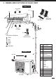
Installation Service 8. INSTALLATION DIENSION DIAGRAM Space to the ceiling 15cm Above Space to the wall 15cm Above 15cm Above Space to the wall 300cm Above Air outlet side 250 cm Above Space to the floor Space to the obstruction 50cm Above • The dimensions of the space necessary for correct installation of the appliance including the minimum permissible distances to adjacent structures.
Installation Service 9. INSTALL INDOOR UNIT 9.1 Install the Real Panel 1. Always mount the rear panel horizontally. Due to the water tray of indoor unit has been adopted the both-way drainage design, the outlet of water tray should be adjusted slightly down when installing, that is taking the outlet of the water tray as the center of a circle, the included angle between the evaporator and level should be 0 or more, that is good for condensing water drainage. 2. Fix the rear panel on the wall with screws.
Installation Service 9. INSTALL INDOOR UNIT 9.4 Connect Indoor and Outdoor Electric Wire Power Supply Wire (1.8m) 1. The power wire and power connection wire are supplied in factory in a fixed length. (Fig.15a, 15b) Wiring Cover Yellow-Green 3 Brown Black N(1) 2 Blue NOTE Do consult your local dealer if additional wire length is required. 2. Open the surface panel and remove the wiring cover. (Fig.15a, 15b) 3.
Installation Service 9. INSTALL INDOOR UNIT 9.4.2 Wire Length and Diameter Regulations on wiring diameter differ from locality. For field wiring requirements, please refer to local electrical codes. Carefully observe these regulations when carrrying out the installation. Table 1 lists the recommended and max. allowable wire lengths and diameters for the power supply system. Please refer to the wiring system diagram (Fig.18 &19) for the meaning of “A”, “B” and "C" in Table 1.
Installation Service 9. INSTALL INDOOR UNIT 9.5 How to Install the Indoor Unit For tubing, choose either the left side or right side direction. 1. When routing the piping and wiring from the left or right side of indoor unit, cut off the tailing from the chassis in necessary. (As shown in Fig 20) • Cut off the tailings 1 when routing the wiring only. • Cut of the tailings 1 and tailings 2 when routing both the wiring and piping. 2.
Installation Service 10. INSTALL OUTDOOR UNIT 10.1 Wiring Instructions for the Outdoor Unit Handle (Cooling Only Model ) 1. Disassemble the handle on the outdoor unit right side plate. (Screw x 1pc) 3 2. Take off wire clamp, connect and fix power connect cord to terminal of line bank. Connect the inter-unit wiring and power line according to the drawing on the handle. Blue Wire clamp 3. Fix the power connection cable with wire clamp. (Fig. 24 / 25) 5.
Installation Service 10. INSTALL OUTDOOR UNIT 10.2 Refrigerant Tubing 10.2.1 Use of The Flaring Method Many of the conventional split system air conditioners employ the flaring method to connect refrigerant tubes which run between indoor and outdoor units. In this method, the copper tubes are flared at each end and connected with flares nuts. 10.2.2 Flaring Procedure With A Flare Tool • Cut the copper tube to the required length with a tube cutter. It is recommended to cut approx.
Installation Service 10. INSTALL OUTDOOR UNIT 10.2.4 Connecting Tubing between Indoor and Outdoor Units • Tightly connect the indoor side refrigerant tubing extended from the wall with the outdoor side tubing. (Fig. 30) • To fasten the flare nuts, apply specified torque as: Table 2 Tube Dia. 6.35 mm Tightening Torque Approx. 15 - 20 N.m (1.5 - 2.0 kg.m) 9.52 mm 12.7 mm Approx. 35 - 40 N.m (3.5 - 4.0 kg.m) Approx. 50 - 55 N.m (5.0 - 5.5 kg.m) Torque wrench Spanner Indoor unit Outdoor unit Fig.30 10.
Installation Service 10. INSTALL OUTDOOR UNIT 10.3 Air Purging Air and moisture remaining in the refrigerant system have undersirable effects as indicated below. Therefore, they must be purged completely. • Pressure in the system rises • Operating current rises • Cooling (or heating) efficiency drops • Moisture in the air may freeze and block capillary tubing. • Water may lead to corrosion of parts in the refrigerant system. Indoor unit Outdoor unit AIR PURGING WITH A VACUUM PUMP (FOR TEST RUN) 1.
Installation Service 10. INSTALL OUTDOOR UNIT 10.3 Air Purging - (Continued) 5. With the vacuum pump still running, close the "Low" knob of the manifold valve. Then stop the vacuum pump. o 90 (1/4 turn) 6. With the accessory hex wrench, turn the valve stem on the narrow tube service valve counter-clockwise by 90 degrees (1/4 turn) for 10 seconds, and then turn the stem clockwise to close it again. (Fig.36) CAUTION Be sure completely insert the hex wrench before attempting to turn the valve. 7.
Installation Service 10. INSTALL OUTDOOR UNIT 10.4 Tubing Length Install unit within the maximum elevation different (H) above or below the outdoor unit and within a tatal tubing length (L) from the outdoor unit as detailed showed in Table 4 and Fig.37. Tubing length (L) INDOOR UNIT Elevation difference (H) OUTDOOR UNIT Fig. 37 Table 4 Model Max.
Installation Service 11. PUMP DOWN 11.1 What is Pump Down? Pump down means collecting all refrigerant gas in system back into the outdoor unit without losing any of gas. Pump down is used when the unit is to be moved or before serving the refrigerant circuit. Indoor unit 11.2 Pump Down Procedure NOTE Be sure to carry out pump down with the unit in cooling mode. 1. Connect the Lo side charging hose of the manifold valve to the service port on the wide tube service valve. (Fig 39) Outdoor unit 2.
Installation Service 12. CHECK AFTER INSTALLATION AND TEST RUN 12.1 Check After Installation Check the items listed in below table after installation of air conditioner. Items to be checked Possible malfunction • Has it been fixed firmly? • The unit may drop, shake or emit noise. • Have you done the refrigerant leakage test? • It may cause insufficient of cooling (heating) capacity. • Is heat insulation sufficient? • It may cause condensation and dripping.