
Installation Guide

© 2016 Halco Lighting Technologies, LLC. All rights reserved. Halco and ProLED are registered trademarks of Halco Lighting Technologies. All sizes and specications are subject to change. 12-16-16.
Halco Lighting Technologies | 2940 Pacic Drive | Norcross, GA 30071 | Toll Free 800.677.3334 | Phone 770.242.3612 | Fax 800.880.0822 | halcolighting.com | Atlanta | Carlstadt | Cleveland | Houston | Los Angeles | Phoenix
ProLED
®
4", 6" and 8" LED Commercial Downlight Retrot Installation
®
Dimming
Dimming performance may depend on the dimmer, the dimmer range adjustment setting (for dimmers with brightness range adjustments), the wiring
method, and/or the number of LED modules installed on the dimmer circuit.
*For dimmer selection, Dimming control manufacturers revise their products often; for the latest list of compatible dimmers please visit our website at
www.halcolighting.com.
*For best results, it is recommended to install a minimum of four LED modules onto one dimmer.
*Before turning on the LED lights, set dimmer position at full brightness before adjusting to a lower light level.
*Please follow the dimming control manufacturer’s instructions for the installation of all dimming controls.
1. TURN OFF THE POWER AT CIRCUIT BREAKER PRIOR TO
INSTALLATION. Remove the diffuser and existing bulb if necessary.
Remove the existing trim.
When running the supply wires, allow for additional 18 inch of wire at
each installation in order to make the electrical connections on the
room side of the ceiling hole.
INSTALLATION INSTRUCTIONS:
This IC/AT xture is intended for use in suspended ceilings(with or without insulation). Shut off power before installation.
CEILING TILE AND SHEETROCK:
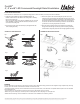
2. Remove the junction box screws holding the junction box cover.
Pass the supply wires through the appropriate knockout hole on the
junction box. Make the electrical connections to t inside the junction
box following the electrical connections. Make sure all connections
are secure, tuck all the wires inside the junction box and reinstall the
junction box cover using the junction box screws.
Fig 1
Fig 2
Fig 3
Fig 4
Fig 5
3. Press the top portion of the remodel clips up and against the side
of the housing assembly.
4. Push the housing assembly with the top side of the remodel clips
through the hole until tight. Continue to push the housing assembly
until the xture snaps into place with the trim tight against the ceiling.
COMMERCIAL RECESSED HOUSING:
Fig 2
Fig 3
Fig 1
Fig 4