Operation and Maintenance Manual for Hale Booster Pumps AP CBP 2CBP ECO NO REV 02-0301 A CHANGED FROM RELEASED BY DATE APVD SAG 10/15/02 MAL HALE PRODUCTS, INC A Unit of IDEX Corporation Conshohocken, PA 19428 USA DRAWN BY: CHECKED BY: SAG PRW ISSUE DATE: 10/15/02 COPYRIGHT © NOT TO BE REPRODUCED OR USED TO MAKE OTHER DRAWINGS OR MACHINERY HALE PRODUCTS, INC.
Booster Contents SECTION I: INTRODUCTION .................................................................... I-1 Overview............................................................................................................................................................. Principals Of Operation ......................................................................................................................... Centrifugal Force ..................................................................
Booster Replace Gearbox Oil ........................................................................................................................... Tank to Pump Flow Rate Test .............................................................................................................. Performance Testing Overview ............................................................................................................. Worn Clearance Rings and Impeller Hubs ...........................................
Booster SECTION VI: PARTS LISTS ...................................................................... 6-1 AP Pump ............................................................................................................................................. 6-2 CBP Pump ........................................................................................................................................... 6-5 2CBP Pump .......................................................................................
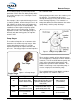
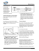
Booster Pumps SECTION I: INTRODUCTION OVERVIEW Hale Products currently has 3 models of booster pumps in production: o o o AP CBP 2CBP shows an amount of water has been placed at the center of a disk. The disk is rotated and the water is thrown outward from the center to the edge of the disk. The velocity at which the water travels from the center directly relates to the diameter of the disk and the speed of rotation.
Booster Pumps The centrifugal pump is preferred by the fire protection service due to its ability to fully utilize any positive inlet pressure, reducing the strain on the pump. For example, if the required discharge pressure is 120 PSI (8 BAR), and the inlet pressure is 45 PSI (3 BAR), the pump must only produce the difference in pressure of 75 PSI (5 BAR). This contributes to low engine and pump speeds which reduces wear on the pump.
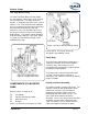
Booster Pumps Two-Stage Booster Pump The Hale Two-Stage Booster Pump (2CBP) has two impellers connected in series for highpressure operation. The output of the first impeller is supplied to the intake of the second impeller. This second impeller adds additional pressure and directs the water to the discharge. Since the two-stage booster pump only operates in series, the final water pressure is the inlet pressure plus the pressure added by both impellers.
Booster Pumps confined to increase acceleration and pressure. The discharging tube is widest at the pump outlet. The increasing discharge path, known as the volute, collects the fast moving water and converts the water's velocity into pressure. engine, and the torque rating of the transmission PTO. Pump Drives There are four common types of booster pump drives used on fire fighting apparatus: Mechanical Seal The mechanical seal is common to all Hale booster pumps.
Booster Pumps NOTE: Please refer to Hale Bulletin #886 for further assistance in selecting the correct booster pump PTO. ACCESSORIES In addition to the basic parts of Hale booster pumps described above, the following items are available to enhance operation: o o o o Cooling Systems Priming Systems Pressure Control Devices Anodes Auxiliary Cooling (Overheat Protection) A cooler is available to protect the gearbox, the apparatus engine, and the pump.
Booster Pumps The Hale ESP-series priming pump is an environmentally friendly primer that does not require a separate lubricant reservoir. The vanes and pump body are self lubricating for maintenance free operation. Figure 1 -10: PVG Priming Valve A Hale priming pump has a single control to open the priming valve between the booster pump and the priming pump, and start the priming motor. Priming Valves Hale priming valves open when the priming pump is operated to allow the air to escape from the pump.
Booster Pumps applied to the diaphragm in the PM Control valve. As the pressure on the diaphragm increases beyond the set point, the stem will move off its seat, allowing pump pressure to push on the piston in the relief valve. The pressure on the piston will cause the relief valve seat to lift allowing excess pressure to dump back to the pump suction. After the pressure equalizes, the piston returns to the closed position. Figure 1-11: TRV-L exceeds 120o F (48.
Booster Pumps EXPLANATION OF TERMS Priming Pump Atmospheric Pressure An auxiliary positive displacement pump which pumps air out of the booster pump creating a vacuum in order to prime the pump. The priming pump is a rotary vane type, electric motor driven. Once the main pump is primed and pumping, the priming pump is shut off. Static air pressure. Air pressure is 14 pounds per square inch at sea level. Pressure increases below sea level and decreases above sea level.
Booster Pumps SECTION II OPERATING PROCEDURES This section supplies information and procedures for the operation of Hale booster pumps. Included in this section are procedures for pumping from an on-board tank, a hydrant, from draft, and post-operation procedures. Unless otherwise indicated, these instructions apply to all Hale booster pumps. THE PROCEDURES IN THIS SECTION ARE GENERAL OPERATING PROCEDURES.
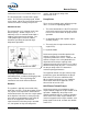
Booster Pumps 13. If the pump overheats and it is not equipped with a Hale TRV valve, open the valve to access the bypass line, if it is furnished, or open the valve to the booster tank (both suction and discharge sides) to circulate water. 14. After completion of pumping operations, gradually reduce the pump pressure until the engine is at idle speed. Disengage the PTO. DRAFT LIMITING FACTORS Figure 2-2: Pump Operator's Panel 11.
Booster Pumps capacity will be reduced. 2. Bring the truck to a complete stop. 3. Apply the truck parking brake. Running the engine at speeds higher than 1200 RPM during priming is not recommended since it will not improve priming operation and may cause damage to the pump. 4. Shift the truck transmission to the NEUTRAL position. REFER TO DEPARTMENT PROCEDURES ON SETTING WHEEL CHOCKS AND HOSES. ALL VALVES, DRAIN COCKS, AND CAPS SHOULD BE CLOSED. 5. Engage pump PTO.
Booster Pumps slightly open the drain line. RELIEF VALVE PROCEDURES 16. After completing pumping procedures, gradually reduce the engine RPM to idle speed and disengage the PTO. TPM /P35 Relief Valve Procedures PUMP AND ROLL OPERATION These procedures cover the Hale TPM Relief Valve System. Be sure to select the correct procedure, for the equipment on the truck. Hale booster pumps are primarily driven by a transmission mounted Power-Take-Off (PTO) unit.
Booster Pumps More complete and detailed information can be found in the relief valve manual. Process of Cavitation 1. When increased discharge demand exceeds the intake, bubbles form in the low-pressure region (eye) of the impeller. THE PRESSURE INDICATOR ON THE PANEL IS ONLY A ROUGH INDICATION OF TPM SETTING. ALWAYS USE THE ABOVE PROCEDURE TO PROPERLY SET THE TPM RELIEF VALVE SYSTEM. CAVITATION Cavitation can occur while pumping from draft, in relay, or from a hydrant.
Booster Pumps Warning Signs of Cavitation: Discharge and Gauges Discharge Pressure In a properly functioning pump, an increase in RPM will increase the discharge pressure and volume. An increase in engine RPM that does not cause an increase in the pump discharge pressure, is the most reliable indication that a pump is approaching cavitation.
Booster Pumps Elevation Feet (Meters) Lift-Loss in Feet (Meters) 2,000 (609) NFPA Baseline Hose Diameters (mm) FLOWS GPM (LPM) 3,000 (914) 1.1 (0.33) 250 4,000 (1219) 2.2 (0.67) 350 5,000 (1524) 3.3 (1) 500 6,000 (1828) 4.4 (1.34) 7,000 (2133) 5.5 (1.67) 8,000 (2438) 6.6 (2.01) 9,000 (2743) 7.7 (2.35) 10,000 (3048) 8.8 (2.68) Table 2-3: Lift Loss from Elevation 750 1000 1250 1500 1750 3" (76) 4" (102) 4 ½" (114) 5" (127) 6" (152) Lift Loss 5.2 (19.7) 2.5 (9.5) 5.0 (19) 11.
Booster Pumps POST OPERATION PROCEDURE o Return the engine to idle. o Slowly close all valves. o Place the transmission in neutral or park. o Slowly shift from "pump" to "road" to disengage the pump. o Drain the pump (especially important in freezing weather): a. Open the discharge valves, remove suction tube caps, and discharge valve caps. b. Open the pump body drain cocks or Hale multiple drain valve. If a multiple drain valve is used, all pump drain lines should be connected to this valve. c.
Booster Pumps SECTION III PREVENTIVE MAINTENANCE o Checking and cleaning the intake strainers OVERVIEW o Verifying all gauges are in working order. Hale Booster Pumps require very little care and maintenance. However, the little required is important. Preventive maintenance tasks take little time to accomplish and consist of leak testing, lubrication and cleaning. The procedures supplied in this section are for normal use and conditions. o Checking any auxiliary engine. o Operating pump controls.
Booster Pumps proper valve operation. 6. Return the relief valve hand wheel and the apparatus to normal operational condition. Pump Shift Warning Indicator Lights VERIFY THE PARKING BRAKE IS SET AND THE WHEELS ARE CHOCKED TO PREVENT ANY MOVEMENT OF THE APPARATUS. 1. Follow the operating procedures in Section II to engage the pump if no local procedures exist. 2. Verify the warning indicators in the cab and the pump control panel function properly. 3.
Booster Pumps until the gauge indicates at least 22 IN-ng vacuum. Monthly Maintenance o Check the Gearbox Oil 4. Compare the readings of the test gauge and the apparatus gauge. Note any difference. o Perform the dry vacuum test o Check the drive line bolts. Gearbox Lubrication Too much oil or the wrong type of oil will result in unnecessary loss of power and high oil temperature. Change the oil every 12 months, depending on pump usage.
Booster Pumps o Place caps on all valves 3. Inspect the magnetic drain plug. If of metal filings are present on the drain plug, remove the cooler or coverplate to visually inspect and clean the internal components. Repair or replace as necessary. o Connect a positive pressure source o Inspect the pump for leaks. Grade 8 Bolt head Figure 3-4 Drive Line and Flange Bolts Check all drive line and flange bolts to ensure: 1. No bolts are missing. 2. All bolts are tight.
Booster Pumps Example PUMP RATING GPM (LPM) CAPACITY PRESSURE PSI (BAR) 250 (946) 350 (1325) 450 (1703) 500 (1893) 750 (2839) 1000 (3785) FULL 150 (10) 250 (946) 350 (1325) 450 (1703) 500 (1893) 750 (2839) 1000 (3785) 70% 200 (13) 175 (662) 245 (927) 315 (1192) 350 (1325) 525 (1987) 700 (2650) 50% 250 (17) 125 (473) 175 (662) 225 (852) 250 (946) 375 (1419) 500 (1893) Table 3-1 4.
Booster Pumps Refer to local procedures for pump testing procedures and practices. For Pitot gauge accuracy, the nozzle pressures should be between 30 and 85 PSIG. See the chart on the facing page for nozzle flow and pressures. Table 3-3 provides GPM for various nozzle sizes. Because NFPA standards specify both GPM and pressure, it is usually necessary to restrict the flow somewhat to build up the pump pressure. In normal pumping, this restriction would be caused by the friction loss in the lines.
Booster Pumps GPM AT VARIOUS NOZZLE SIZES Nozzle Size ¾” 7/8” 1" 1 1/8" 92 125 163 206 99 135 176 222 106 144 188 238 112 153 199 252 118 161 210 266 124 169 220 279 130 176 230 291 132 179 234 296 134 182 238 301 136 185 241 305 138 188 245 310 140 190 248 315 142 193 252 319 144 196 255 323 146 198 259 328 148 201 262 332 150 203 266 36 154 210 274 347 159 216 282 357 163 222 289 366 167 228 297 376 171 233 304 385 175 239 311 394 179 244 319 403 183 249 325 412 1 ¼” 254 275 294 311 328 344 360 366 371 3
Booster Pumps performance has dropped appreciably compared to its original performance, it needs to be serviced. (Apparatus test results should be on file with the delivery documents. If not, they may be obtained from the apparatus manufacturer or from the original certifying authority.) requires that the impellers also be replaced. See Section V for maintenance and repair information if pump disassembly is required.
SECTION IV: TROUBLESHOOTING Table 4-1 lists the symptoms of some common problems and possible corrective measures. Before calling Hale or a Hale authorized parts service center for assistance, eliminate problem causes using this guide. If the problem cannot be corrected, please have the following information ready prior to calling the Hale Customer Service Technician Department for assistance. Customer Service Number: 1-800-720-3473.
CONDITION PUMP LOSES PRIME OR WILL NOT PRIME (cont'd.) POSSIBLE CAUSE SUGGESTED CORRECTION Suction lift too high Do not attempt lifts exceeding 22 feet. Restricted suction strainer Remove obstruction from suction hose strainer. Suction Connections Clean and tighten all suction connections. Check suction hose and hose gaskets for possible defects. Primer not operated long enough. Proper priming procedures should be followed. Do not release the primer control before assuring a complete prime.
CONDITION PUMP LOSES PRIME OR WILL NOT PRIME (Cont'd.) POSSIBLE CAUSE Air Leaks (cont'd.) SUGGESTED CORRECTION 3. After priming, shut off the engine. Audible detection of a leak is often possible. 4. Connect the suction hose from the hydrant or the discharge of another pumper to pressurize the pump with water, and look for visible leakage and correct. A pressure of 100 PSI (6.9 BAR) should be sufficient. Do not exceed pressure limitations of pump, accessories, or piping connections. 5.
CONDITION POSSIBLE CAUSE SUGGESTED CORRECTION INSUFFICIENT PUMP CAPACITY (cont'd.) Relief Valve improperly set If the relief valve control is set too low the relief valve will open and bypass water. Reset the relief valve control per the procedures in Section III. Other bypass lines (such as foam system or in-line valves) may reduce pump capacity or pressure.
CONDITION RELIEF VALVE DOES NOT RELIEVE PRESSURE WHEN VALVES ARE CLOSED RELIEF VALVE DOES NOT RECOVER AND RETURN TO ORIGINAL PRESSURE SETTING AFTER OPENING VALVES WATER IN PUMP GEARBOX Troubleshooting POSSIBLE CAUSE SUGGESTED CORRECTION Worn pump impeller(s) and / or clearance rings Installation of new parts required. Impeller blockage Blockage in the impeller can prevent loss of both capacity and pressure. Back flushing the pump from discharge to suction may free blockage.
CONDITION POSSIBLE CAUSE DISCHARGE VALVES DIFFICULT TO OPERATE Lack of lubrication SUGGESTED CORRECTION Recommended weekly lubrication of discharge and suction valve, use an approved lubricant. Refer to the valve manual for more information. Cavitation Troubleshooting Pump is beginning to cavitate Discharging more water than the pump is taking in. Increase the flow into the pump with more and/or larger intake lines. Gate the discharge valves to reduce flow and maintain pressure.
CONDITION POSSIBLE CAUSE SUGGESTED CORRECTION Rotation Symptoms It is possible to reassemble the pump incorrectly or with the wrong parts. Always compare the replacement parts with the original hardware. Contact customer service at Hale Products to answer questions or concerns. Wrong impeller installed Verify the new impeller vanes are oriented the same as the old impeller before installing. See figure 4-3. Impellers installed backwards (2CBP) Verify the impellers are in the correct order.
Sec IV- 8 Troubleshooting
Booster Pumps SECTION V MAINTENANCE AND REPAIR 5. Use only PAC-EASE Rubber Lubricant Emulsion (or equal) on the rubber mechanical seal parts to ease installation. OVERVIEW This section describes the removal, inspection, and re-installation (as required for maintenance and repair) of all booster pump components. To completely disassemble the pump and gearbox, follow the disassembly instructions in the order which they appear in this text.
Booster Pumps Model Gearbox Oil Capacity AP 1 ¾ QTS. (1.66L) CBP CBP2 & 3 = 1 ¾QTS. (1.66L) CBP4 & 5 = 1 QT. (.95L) 2CBP 2CBP2 & 3 = 1 ¾QTS. (1.66L) 2CBP4 & 5 = 1 QT. (.95L) Table 5-1: Oil Capacity Table Bolt Size Material Maximum Torque ft-lb (n-m) 5/16-18 zinc-plated steel 17 (23) 5/16-18 zinc-plated steel w/360o nylon lock 19 (26) 5/16-18 silicon bronze 10.
Booster Pumps 6. Replace any hardware that shows signs of excessive wear. PUMP COMPONENTS 7. When inspecting the impellers and clearance rings for wear, measure the impeller hub diameter and the inner diameter of the clearance ring. Compare these measurements to data in Table 5-3. If measurements indicate, obtain replacement clearance rings and impeller.
Booster Pumps 7. Disconnect airlines, electrical switches, and the tachometer cable as required. 8. Attach a proper lifting device before loosening or removing mounting brackets. 9. Disconnect mounting brackets to remove the pump and gearbox assembly. 10. Place the pump and gearbox assembly on a stable work stand. The air vent and gearbox cover are exposed. This will provide easy and safe access to the internal components.
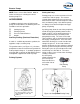
Booster Pumps 4. Remove all remaining gasket material from the mating surfaces of the pump body and pump head. Install the Pump body 1. Use a press to install the clearance ring in the pump body. 2. Apply a small amount of grease to the gasket and align on the pump body. 3. Install the pump body onto the pump head, do not damage the clearance rings or impeller. Figure 5-4: AP Pump and Gearbox Assembly AP PUMP DISASSEMBLY 4.
Booster Pumps DO NOT STRIKE THE IMPELLER. IRREPARABLE DAMAGE MAY RESULT. 5. Inspect and clean all components according to the Cleaning and Inspection Guidelines above. 4. Carefully slide the stationary seat over the pump shaft and fit the stationary seat of the mechanical seal into the pump head. 5. Carefully push the stationary seat into the pump head bore using a soft clean pusher tube. Verify the stationary seat is firmly seated in the pump head. 6. Clean the pump shaft with alcohol swabs.
Booster Pumps Figure 5-5: AP Pump and Gearbox for Parts Identification 2. Remove the 7/16-14 X 1" long cap screws that secure the pump head to the gearbox. 3. With the cap screws removed, pull the pump head from the gearbox. Do not to damage the pump shaft. the pump head. 7. Inspect and clean all components according to the Cleaning and Inspection Guidelines above. REINSTALL AP PUMP HEAD 4. Scrape the gasket from the mating surfaces of the pump head and gearbox. 5.
Booster Pumps align on the pump head. 3. Install a new seal ring into the bore of the pump head on the gearbox side. 4. Install the pump head on the gearbox, do not damage the oil seal or pump shaft. 5. Apply Loctite™ 242 (or equal) and install the four 7/16-14 UNC x 1 cap screws to secure the pump head to the gearbox. Tighten capscrews to 40 ft-lb (54 Nm). AP Gearbox Disassemble AP Gearbox See figure 5-5 for parts identification. 8. Remove the oil seal from the drive shaft then remove the retaining ring.
Booster Pumps shaft into the gearbox housing bore. 6. Install the retaining ring to hold the bearing and drive shaft in place. in the water manifold. 18. Reinstall the pump onto the apparatus and check for leaks. 7. Install a new oil seal. 8. Lift the gearbox onto its base. Apply Loctite 242 and install the 1/2-13 UNC set screw in the drive shaft until it is flush with the gearbox housing. 9. Set the gearbox flat with the drive shaft facing down. 10.
Booster Pumps Figure 5-7: CBP for Parts Identification Sec V- 10 Maintenance and Repair
Booster Pumps CBP PUMP REPAIR Please review the General Repair and Cleaning and Inspection Guidelines before beginning these procedures. CBP Pump Body The pump body can be removed while the pump and gearbox assembly are mounted on the apparatus. With the pump body removed, the impeller can be serviced without removing the entire pump and gearbox assembly. Remove CBP Pump Body 1. Disconnect the suction, discharge, cooling lines, and electrical switches. Disconnect the mounting brackets as required.
Booster Pumps Reinstall CBP Impeller 1. Install the impeller key in the keyway on the pump shaft. Carefully slide the impeller over pump shaft aligning the keyway with the impeller key. 2. Install the lock washer on the pump shaft. 3. Coat the pump shaft threads with Loctite™ 640 and install the impeller nut. 4. Hold the impeller with a strap wrench, and tighten impeller nut. Torque to 125 ft_lbs 169.5 (Nm). 5. Stake the lock washer to lock the impeller nut in place. 6.
Booster Pumps described. CBP GEARBOX Remove and Disassemble CBP Gearbox Figure 5-8 Do not damage the pump shaft. 4. Remove the gasket material from the mating surfaces of the pump head and gearbox. 5. Remove the oil seal and mechanical seal seat from the pump head. 6. Inspect and clean all components according to the Cleaning and Inspection Guidelines above. Reinstall CBP Pump Head 1. Use a press to install a new oil seal in the pump head. 2.
Booster Pumps 10. With the set screw removed, insert a drift punch into the 1/2-13 hole and begin pushing the drive shaft from gearbox while protecting the drive gear from falling. 11. Once the shaft is clear of gearbox, remove drive gear from housing. 12. Remove the two 207K bearings from the drive shaft and gearbox housing. 5. Install the other 207K bearing over the drive shaft into the gearbox housing bore. 6. Install the retaining ring to hold the bearing and drive shaft in place. 7.
Booster Pumps Figure 5-11: 2CBP for Parts Identification Maintenance and Repair Sec V- 15
Booster Pumps 2CBP PUMP REPAIR Please review the General Repair and Cleaning and Inspection Guidelines before beginning these procedures. 7. Hold the impeller with a strap wrench. Use a 1 3/4" socket or wrench to remove the impeller nut and washer. 8. To avoid warping, use a puller to remove the impellers. Remove the center bearing, and impeller key from the shaft. Because the 2CBP differs in construction from other booster pumps, servicing any internal part demands complete disassembly as outlined here.
Booster Pumps o Apply a generous coating of PAC-EASE Rubber Lubricant Emulsion (or equal) to the outside of the stationary seat. o Slide the stationary seat over the pump shaft and fit the stationary seat of the mechanical seal into the pump head. o Push the stationary seat into the pump head bore using a soft clean pusher tube. The stationary seat must be seated in the pump head. o Clean the pump shaft with alcohol swabs.
Booster Pumps lower pump body. 10. If previously removed, insert the dowel pins into the lower pump body 11. Install the upper pump body and secure it to the pump head with the five 1/16-18 X 3/4" capscrews. Insert the four 15/16-18 X 3/4 screws, washers and nuts into both pump halves. 12. Verify the bearings and spring pin are in the bearing housing. Apply a light coat of grease to hold the gasket in place then install the bearing housing onto the pump body. 13.
Booster Pumps Reassemble and Reinstall 2CBP Gearbox 1. Place the gearbox housing on a steady flat surface with drive shaft opening facing up. 2. Insert one of the two 207K bearings into the bore of the gearbox housing. 3. Slide the drive gear into the gearbox housing. Align the bore of the drive gear with the bore of the gearbox housing. 4. Insert the key in the drive shaft and insert the drive shaft into the gearbox housing. Press the driveshaft into the 207K bearing. install the gasket and bearing cover.
Booster Pumps Maintenance Kits Disassembly of the pump and/or gearbox is a major undertaking that can remove a pump from service for a considerable period of time. Gaskets must be replaced to ensure the pump is fully operational when returned to service. It is never permissible to reassemble the pump without installing new gaskets. Hale Products supplies repair kits designed specifically for each pump and gearbox. Other parts can be ordered by calling Hale Products Customer Service at 1-800-220-3473.
Booster SECTION VI: PARTS LISTS This section contains part lists and exploded views for the following Booster Pump models: o AP o CBP o 2CBP o Hydraulic Drive Option o Tachometer Option Parts Lists Sec VI-1
Booster Figure 6-1 AP Pump Sec VI-2 Parts Lists
Booster AP Booster Pump Item 1 2 3 Qty 1 1 Part Number Description 001-0750-00-0 AP PUMP BODY 001-0750-01-0 AP PUMP BODY (OPP ENG) BRASS 001-0750-02-0 AP PUMP BODY (4.5 ISO) O.E. ROT 001-0750-03-0 AP PUMP BODY (4-1/2 NST) O.E.ROT 001-0750-04-0 AP PUMP BODY(4"NPT)O.E.ROT. 001-0760-00-0 AP PUMP BODY 001-0760-01-0 AP PUMP BODY (ENG ROT) BRASS 001-0760-02-0 AP PUMP BODY (4.5 ISO) ENG ROT 001-0760-03-0 AP PUMP BODY (4-1/2 NST) ENG ROT 001-0760-04-0 AP PUMP BODY(4"NPT)ENG.ROT.
Booster Item No.
Booster Figure 6-2 CBP Pump Parts Lists Sec VI-5
Booster CBP Series Pump Item # Part Number 001-0190-00-0 1 001-0190-01-0 001-0200-00-0 CBP-320LD BODY-VOLUTE(OPP.END) 1 001-0200-01-0 2 3 4 5 002-0170-00-0 002-0170-01-0 004-0091-00-0 004-0380-00-0 008-0150-00-0 016-0230-00-0 016-0240-00-0 Description Qty CBP-B320LD BODY-VOLUTE(O.E.) CBP-320LD BODY-VOLUTE ENG ROT CBP-B320RD BODY PUMP(ENG.
Booster Item # Part Number Qty 23 046-5270-01-0 1 CBP D U GASKET 24 077-1180-05-0 1 78S118 RETAINING RING 25 077-2810-00-0 1 79S281 RETAINING RING 26 097-0810-01-0 12 WASHER-5/16 STL ZINC PL FLAT 27 097-0960-00-0 1 WASHER. 28 101-0082-00-0 1 GEARBOX SERIAL NUMBER PLATE 29 110-2701-11-0 1 NUT-3/4-16 NYL LOCK STNLS JAM. 30 217-0201-00-0 5 1/4 NPT SQUARE HEAD STEEL PLUG 31 217-0301-00-0 4 PLUG-3/8 NPT SQUARE HEAD. 32 217-0401-00-0 2 PLUG-1/2 NPT M.I..
Booster Figure 6-3 2CBP Pump Sec VI-8 Parts Lists
Booster 2CBP PARTS LIST Item # 1&2 3 4 5 6 7 Part Number Qty Description 001-0230-00-0 1 2CBP PUMP BODY 001-0230-03-0 1 2CBP PUMP BODY BRONZE 002-0180-00-0 002-0180-01-0 004-0091-00-0 004-0380-00-0 007-0260-00-0 007-0260-01-0 007-0270-00-0 007-0270-01-0 007-0280-00-0 007-0280-01-0 1 1 1 1 1 2CBP-2D HEAD-PUMP 2CBP-2D HEAD-PUMP BRONZE CBP GEARBOX HSG 40FW DRIVE UNIT HSG 2CBP CROSS OVER TUBE 2CBP CROSS OVER TUBE BRONZE 2CBP-283 TUBE-DISCHARGE 2CBP-283 TUBE-DISCHARGE BRONZE 2CBP-75 ADAPTER-SUCTION
Booster Item No.
Booster Item No. 53 54 Part no 217-0401-08-0 217-0501-00-0 217-0501-01-0 Qty 1 1 Description PLUG-1/2 NPT M.I. MAGNETIC PLUG-3/4 NPT M.I.
Booster HYDRAULIC ADAPTER Hydraulically driven booster pumps are equipped with a drive adapter. The adapter bolts to the standard pump gearbox. Use the part list below for reference when contacting Hale Products for service.
Booster TACHOMETER OPTION Connected to the pump shaft at the gearbox, the tachometer take off provides for an actual RPM of the pump when connected to a tachometer. The ratio adapter is a 10:1 reduction of the actual rotation of the shaft. The drawing and parts list below illustrate the standard installation of the assembly.
Booster LIMITED WARRANTY EXPRESS WARRANTY. Hale Products Inc. (“Hale”) hereby warrants to the original buyer that products manufactured by Hale are free of defects in material and workmanship for two (2) years or 2000 hours usage, whichever shall first occur. The “Warranty Period” commences on the date the Product is first placed in service. LIMITATIONS. HALE’S obligation is expressly conditioned on the Product being: • Subjected to nominal use and service.