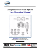
Compressed Air Foam System User Operation Manual Hale Products Inc. ◆ A Unit of IDEX Corporation 700 Spring Mill Avenue ◆ Conshohocken, PA 19428 U.S.A. Telephone: 610-825-6300 ◆ FAX: 610-825-6440 Web: www.haleproducts.
APPARATUS INFORMATION ENGINE ______________________________________________ TRANSMISSION _______________________________________ MAXIMUM CAFS ENGINE RPM ___________________________ CAFS ENGINE SPEED RANGE ___________________________ NOTICE ! Class1 cannot assume responsibility for product failure resulting from improper maintenance or operation. Class1 is responsible only to the limits stated in the product warranty. Product specifications contained in this manual are subject to change without notice.
Table of Contents ❑ Contents Page CAFSPro User Operations Manual 1 Safety Precautions...................................................................................7 1.1 Safety Guidelines ................................................................................................... 7 2 How the CAFSPro System Works.......................................................13 Figure 2-1: Normal Compressed Air Foam System ...............................................
❑ Table of Contents Contents - continued Page 3.1 Engine Controls and Indicators - continued Audible Alarm .............................................................................................................. 27 Figure 3-8: Audible Alarm ...................................................................................... 27 4 Basic Operation....................................................................................
Table of Contents ❑ Contents - continued Page 4a.1 Water Supply - continued Duplex Master Pressure Gauge ................................................................................... 44 Hale FoamLogix Control Unit ....................................................................................... 44 Hale CAFSPro Display Unit ......................................................................................... 45 Wet and Dry Foam ..............................................................
❑ Table of Contents Contents - continued Page 7.5 Air Cleaner Element .............................................................................................56 7.6 Compressor Belt Tension Adjustment ...............................................................56 General .............................................................................................................................. 56 Figure 7-2: Removing the Belt Guard ................................................................
Safety Precautions ❑ 1 Safety Precautions IMPORTANT ! THE HALE CAFSPRO® PUMP SYSTEM (OR CAFSPRO) IS DESIGNED FOR OPTIMUM SAFETY OF ITS OPERATORS. FOR ADDED PROTECTION, PLEASE FOLLOW THE SAFETY GUIDELINES LISTED IN THIS SECTION AND ADHERE TO ALL WARNING, DANGER, CAUTION AND IMPORTANT NOTES FOUND WITHIN THIS MANUAL. THIS SECTION ON SAFETY MUST BE CAREFULLY READ, UNDERSTOOD AND ADHERED TO STRICTLY BY ALL INSTALLERS AND OPERATORS BEFORE ATTEMPTING TO INSTALL OR OPERATE THE CAFSPRO PUMP SYSTEM.
❑ Safety Precautions ❑ Before attempting to start the CAFSPro make sure to close all manual drains and discharge valves. ❑ Adding compressed air to the hose line dramatically increases the energy content. Hose lines charged with compressed air foam have very little weight but contain large amounts of energy. ❑ CAFS Systems add power to the fire stream via compressed air. Proper education, training and nozzle selection are required for operational effectiveness and safety.
Safety Precautions ❑ ❑ DO NOT perform maintenance on the Hale CAFSPro system while the unit is running. Make sure the system is shut down and components have cooled before attempting maintenance. ❑ The operating pressure range of the CAFSPro compressed air foam system is 75-150 psi (5.2-10.4 BAR). WARNING ! DO NOT EXCEED 150 PSI (10.3 BAR). ❑ Do not use a pump pressure governor in the pressure control mode with a CAFS system.
❑ Safety Precautions WARNING ! NO MODIFICATIONS OR ADDITIONS MAY BE MADE TO THE CAFSPRO PUMP SYSTEM WITHOUT PRIOR WRITTEN PERMISSION FROM: Hale Products, Incorporated Fire Suppression Division 700 Spring Mill Avenue Conshohocken, PA 19428 U.S.A. Telephone:......610-825-6300 Fax:.................610-825-6440 Web .............www.haleproducts.com 10 ❑ To prevent electrical shock always disconnect the primary power source before attempting to service any part of the Hale CAFSPro pump system.
Safety Precautions ❑ CAFSPro User Operation Manual p/n: 029-0020-75-0 ❑ DO NOT mount a radio transmitter or transmitter cables in direct or close contact with the CAFSPro control unit. Direct contact could cause electrical interference and disrupt the control panel or radio operations. ❑ DO NOT connect the foam pump main power lead to small leads that are supplying some other device, such as a light bar or siren. The Hale FoamLogix Model 3.3 and Model 5.
❑ Safety Precautions Notes ______________________________________________________________________ ______________________________________________________________________ ______________________________________________________________________ ______________________________________________________________________ ______________________________________________________________________ ______________________________________________________________________ __________________________________________________________
Overview ❑ 2 How the CAFSPro System Works A normal Compressed Air Foam System (CAFS) combines the fire-fighting properties of water and foam concentrate along with the power of compressed air. (See Figure 2-1: ‘Normal Compressed Air Foam System.’) Figure 2-1: Normal Compressed Air Foam System The Hale CAFSPro® system controls the combination of three components, water, foam concentrate and compressed air – to make compressed air foam.
❑ Overview Figure 2-2: Hale CAFSPro Compressed Air Foam System The Hale FoamLogix foam proportioning system uses a rugged Class 1 flow sensor to measure water flowing out the foam capable discharge(s). The Hale FoamLogix control unit has a computer chip that constantly compares the water flow and foam concentrate flow rates to inject the proper amount of foam concentrate based on the operator selected injection rate. The operator can select any foam concentrate injection rate at the control unit from 0.
Overview ❑ Foam solution is available once the foam concentrate is added to the fire pump discharge. Discharge valves, plumbed into the system, provide foam solution, not CAFS. To obtain CAFS, air must be added to create compressed air foam. The Compressor System is designed to deliver continuous duty performance. Compressed air is added proportionally into the foam solution flow, controlled by the CAFSPro controller. The CAFSPro monitors the air flow and provides a digital readout on the control panel.
❑ Overview ❑ Nozzle Reaction/Compressibility of Air Compressed air foam hose lines, by definition, contain a mixture of compressed air, foam and water. Since compressed air stores energy, a surge is felt when opening the nozzle as the air escapes. Open the nozzle slowly to minimize this surge. Also see Section “1 Safety Precautions” on page 7 for additional nozzle reaction information.
Overview ❑ In addition to the normal hydraulics at work in a fire ground operation, using CAFS also adds pneumatics. Therefore, “hydro-pneumatics” is the governing physics at work when using CAFS. Pump operators and firefighters should keep the following items in mind: WARNING ! ADDING COMPRESSED AIR TO THE HOSE LINE WILL DRAMATICALLY INCREASE THE ENERGY CONTENT. IF PERSONNEL ARE NOT PREPARED, A DANGEROUS SITUATION CAN RESULT.
❑ Overview Air is not allowed to flow into the discharge unless water flow and pressure are available. The Hale FoamLogix system is activated and starts the foam concentrate injection when the air compressor is engaged. This important safety enhancement feature helps to prevent “slug flow” or air and water only from being discharged into the hose line. If the water pump is not primed, or the Hale FoamLogix foam system is OFF or out of foam, the Hale CAFSPro control does not allow air injection.
Overview ❑ Figure 2-4: CAFSPro Pump System Overview CAFSPro User Operation Manual p/n: 029-0020-75-0 19
❑ Overview Notes ______________________________________________________________________ ______________________________________________________________________ ______________________________________________________________________ ______________________________________________________________________ ______________________________________________________________________ ______________________________________________________________________ ____________________________________________________________________
Controls and Indicators ❑ 3 Controls and Indicators Figure 3-1: Operator Panel Arrangement CAFSPro User Operation Manual p/n: 029-0020-75-0 21
❑ Controls and Indicators The operator panel of the apparatus contains controls and indicators that are necessary for its operation and for operation of the CAFSPro Pump System. Before operating the apparatus and CAFSPro, the operator must become familiar with the location and function of these controls. The following is a summary of the controls and indicators used during operation of the CAFSPro system, along with a description of their function. (See Figure 3-1: ‘Operator Panel Arrangement’ on page 21.
Controls and Indicators ❑ Master Pump Suction Gauge This gauge indicates the water pressure delivered to the fire pump through the suction connection, where provided by the apparatus builder. Line Discharge Pressure Gauge This gauge provides an indication of the hose line pressure on the system discharges, where provided by the apparatus builder. Hale FoamLogix Controls and Indicators (See Figure 3-1: ‘Operator Panel Arrangement’ on page 21.
❑ Controls and Indicators The bar graph LEDs light when foam concentrate is being injected, indicating the approximate capacity of the foam concentrate system that is being used. The ARROW buttons control the foam concentrate injection rate. Optional Dual Tank System (See Figure 3-3: “Dual Tank Selectors.”) An optional dual tank system, air or manually operated, allows the operator to select the foam concentrate source.
Controls and Indicators ❑ The Hale MST provides the pump operator with a panel mounted control for flushing the Hale FoamLogix foam proportioning system after completion of Class “B” foam operations. (See Figure 3-4: ‘Manual Single-Tank Flush Selector’ on page 24.) A switch on the MST signals the Hale FoamLogix whether the MST is in the FOAM TANK or FLUSH position. FS Series Foam Strainers (See Figure 3-5: “FS Series Strainers.
❑ Controls and Indicators Hale Instruction Placard (See Figure 3-6: “Hale Single and Dual Tank Instruction Placards.”) Figure 3-6: Hale Single and Dual Tank Instruction Placards These optional placards provide basic instructions for single or dual tank operation of the Hale FoamLogix Foam Proportioning System. They are normally placed on the operator’s panel to meet NFPA requirements for a “System Diagram.” Hale CAFSPro Display (See Figure 3-7: “Hale CAFSPro Control Unit.
Controls and Indicators ❑ The WET and DRY ARROW buttons change the type of CAF discharge produced. The LED bar graph shows the finished CAF consistency, dependent on the number of LEDs that light. CAUTION ! DO NOT EXCEED 195°F (91°C) DURING AIR COMPRESSOR SYSTEM OPERATION. Audible Alarm (See Figure 3-8: “Audible Alarm.”) The audible alarm is mounted on the operator panel.
❑ Controls and Indicators Notes ______________________________________________________________________ ______________________________________________________________________ ______________________________________________________________________ ______________________________________________________________________ ______________________________________________________________________ ______________________________________________________________________ _____________________________________________________
Operation ❑ 4 Basic Operation IMPORTANT ! HALE PRODUCTS, INC. MANUFACTURES QUALITY PUMPS AND FOAM SYSTEMS. HALE RECOMMENDS ADDITIONAL TRAINING IN STRATEGY AND TACTICS OF USING CAFS BY THE AUTHORITY HAVING JURISDICTION. THIS MANUAL IS A SIMPLE GUIDE TO CAFSPRO FOAM SYSTEMS. ADDITIONAL PUMP OPERATION TRAINING IS REQUIRED. BEFORE OPERATING YOUR NEW CAFSPRO SYSTEM, PLEASE REVIEW THIS MANUAL IN ITS ENTIRETY AND VIEW THE COMPANION VIDEO (HALE P/N: 029-9030-00-0).
❑ Operation 4.1 TURN OFF CAFSPRO AND FOAMLOGIX (See Figure 4-1: ‘Typical CAFSPro System Operator Panel Control Arrangement’ on page 29.) CAFSPro turns ON automatically when the pump is engaged. It must be turned OFF for plain water operation. 4.2 1. Press the ON button on the CAFSPro control (right control unit with blue face) to STOP air injection. All capable foam discharges now discharge foam solution. 2.
Operation ❑ Air, from the air compressor, passes through the oil reservoir/separator, where the oil is removed from the air stream. The air then passes from the reservoir to the air injection point on the foam manifold. Air is also provided to an auxiliary outside air powered accessory, if supplied. Stainless-Steel X-type mixers provide a Hale-exclusive, superior mixing action that combines the water, foam concentrate, and air inside the manifold.
❑ Operation Note: The typical preset for the foam proportioning system is to inject Class A foam concentrate into the water stream at 0.5%. This value can be set to 0.3%, 0.4% or any other percentage the department deems appropriate. Normally CAFS operates between 0.3% and 0.5% Class “A” foam. Class “B” foams are proportioned at their listed percent, usually 1% or 3%. Simply throttle up to the desired operating pressure, normally 90 to 100 PSI (5.5 to 6.0 BAR), and open the appropriate discharge valve.
Operation ❑ Preset to 0.5%, this can be increased or decreased at any time using either the up or down arrows, located directly beneath the LED display. (See Figure 4-2: ‘Hale FoamLogix Control Unit’ on page 32.) ❑ TOTAL FLOW - is an indicator of the total volume of foam solution (liquid) that has moved out of the fire pump foam capable discharges since the system was last powered up or reset to zero.
❑ Operation ❑ AIR TO FOAM SOLUTION RATIO - The air-to-foam ratio shows the consistency of the compressed air finished-foam that is being produced. For WET foam, a range of 0.5 SCFM to 1 GPM is available. For the DRIEST foam, up to 11 SCFM is available for every GPM (LPM). This is adjustable using the WET or DRY ARROW buttons. (See Figure 4-3: ‘Hale CAFSPro Control Unit’ on page 33.).
Operation ❑ There are three critical items in the water flow path from the intake side of the pump and finally out of a hose line, i.e., the fire pump, the foam concentrate injection point, and finally, the air injection point. The Hale CAFSPro system uses integrated check valves, constructed of stainless steel, between all three points. The check valves ensure that at no point can air or foam concentrate flow back into the fire pump.
❑ Operation Five seconds after system activation the tank-to-pump valve can be operated manually – CLOSED by the operator. When a CAFS line is pulled and its corresponding discharge valve is opened, compressed air foam is available at CAFS hose line. Adjusting foam consistency from extremely WET to “shaving cream DRY” is done by pressing the WET or DRY ARROW buttons (to adjust the air-towater ratio). The system starts at WET attack CAFS foam of 0.5 SCFM air to 1.0 GPM (3.8 LPM) solution.
Operation ❑ Compressor The compressor is powered by the fire pump gear box. An air clutch automatically engages when the gear box is shifted from ROAD to PUMP. The clutch engagement: ❑ Allows the production of instant compressed air foam from the time the first hand line is opened ❑ Provides a means of controlling the air compressor The compressor is water cooled, using water from the fire pump. It is important to maintain pump circulation in order to avoid overheating the fire pump and compressor.
❑ Operation To operate the ADT, simply switch the toggle switch between positions A and B, passing the “FLUSH” or center position. An indicator light illuminates next to the position selected indicating the change has been successful. The ADT flushes the foam concentrate manifold when you pause between foam types to prevent congealing that occurs when Class “A” and Class “B” foam concentrates mix.
Operation ❑ For your safety, Hale has designed a self-bleed mechanism into the CAFS manifold. As a precaution against air-energized manifolds, when the pump is switched back to ROAD, the CAFS manifold drains itself, then the drain automatically closes. The manifold is still WET and can even contain some residual pressure, but the higher pressures and stored energy have been safely drained to the ground.
❑ Operation IMPORTANT ! - continued A COMPRESSED AIR FOAM SYSTEM (CAFS) IS A VALUABLE FIRE FIGHTING TOOL. HOWEVER, PROPER OPERATION AND TACTICAL USE MUST BE ADDRESSED THROUGH TRAINING AND EDUCATION. THIS MANUAL COVERS THE BASIC OPERATION OF THE HALE CAFSPRO SYSTEM AND DESCRIBES A BASIC SYSTEM ONLY. FURTHER EDUCATION AND TRAINING ON FOAM AND COMPRESSED AIR FOAM IS REQUIRED FOR EFFECTIVE AND SAFE FIRE FIGHTING USE OF THIS EQUIPMENT.
Operation ❑ When a suitable booster tank with direct fill is available, running the pressurized water source into the tank, and running the CAFSPro system while taking suction from the tank, eliminates the problem of higher water pressure than desired. Gating the pump discharges reduces hand line pressure when water is flowing. However, when the nozzle is closed momentarily, line pressures rise to meet master pump pressure. This makes nozzle reaction excessive when the nozzle is again opened.
❑ Operation Engage Pump 1. Once water supply is established, shift the apparatus from ROAD to PUMP using approved departmental procedures. 2. Shifting to PUMP also opens the tank to pump valve, engages the FoamLogix and CAFSPro systems, and the compressor clutch. Establish Discharge Pressure 1. With the system engaged, operate the apparatus as you would during normal water pump operation. 2. Bring the water master discharge pressure up to a suitable pressure [100 PSIG (7 BAR)]. 3.
Operation ❑ WARNING ! CAFS SYSTEMS ADD POWER TO THE FIRE STREAM VIA COMPRESSED AIR. PROPER EDUCATION, TRAINING AND NOZZLE SELECTION IS REQUIRED FOR OPERATIONAL EFFECTIVENESS AND SAFETY. NOZZLE REACTION GREATER THAN THAT OF PLAIN WATER IS TO BE EXPECTED. Set Relief Valve (See Figure 4-7: ‘Relief Valve Control.’) CAFSPro User Operation Manual p/n: 029-0020-75-0 1. When operating from draft, or the apparatus booster tank, the engine maintains correct speed for proper air compressor operation. 2.
❑ Operation Note: A direct tank fill separates the pump intake from the positive supply pressures and allows the pump and CAFS to operate independently of the high pressure supply for easier operations. Hale offers an automatic direct tank fill that allows continuous operation without operator action. Open Discharge Valve(s) Open the discharge valve(s) to charge the discharge line(s). Open CAFS Discharge Slowly open the nozzle on the CAFS hose line to begin compressed air foam fire operation.
Operation ❑ Hale CAFSPro Display Unit ❑ Air Flow ....................................................... 70 SCFM (50 NCMH) Wet and Dry Foam When the CAFSPro system is energized the CAFSPro display unit is set for WET 0.5% attack foam – a concentrate of approximately 0.5 SCFM (0.3 NCMH) air to 1.0 GPM (3.8 LPM) foam solution. The foam type is adjustable from WET (0.5%) to DRY (11.0%) by pressing the DRY button. Three stages of CAFS are available: ❑ WET 0.5% to 1.5% ❑ MEDIUM 1.75% to 3.0% ❑ DRY 11.
❑ Operation Note: Set electronic governor to RPM mode during CAFS operation. 5. Open discharge valve to charge CAFS hose line with water. 6. Slowly open CAFS hose nozzle to begin CAFS operations. 7. Monitor water and air flows and pressures. 8. Adjust apparatus throttle to maintain safe CAFS discharge of about 100 to 125 PSI (6.9 to 8.6 BAR) pressure. 9. Adjust foam consistency (WET to DRY) by pressing UP or DOWN ARROW buttons on the CAFSPro display to the required foam discharge. 4B.
System Shutdown ❑ 5 System Shutdown Proper shutdown procedures prolong the life of the CAFSPro system and ensure the system is ready for operation when needed. 5.1 FOR SYSTEM SHUTDOWN 1. Turn the air injection OFF by pressing the i (ON) button on the CAFSPro control unit. The display reads STBY. 2. Turn the Hale FoamLogix foam proportioning system OFF by pressing the i button on the control unit. Also see FoamLogix Operation and Maintenance Manual, Hale p/n: 029-0020-68-0.
❑ System Shutdown 5. Shift pump from PUMP to ROAD mode. 6. The discharge manifold drain opens long enough (approximately 10 seconds) to drain some residual pressure from the manifold. The pump remains left wet. Note: The tank-to-pump valve CLOSES automatically. 7. Shut OFF the apparatus and perform scheduled maintenance and stowage of equipment. 8. Drain pump if SOPs require it. WARNING ! PROJECTILES CAN CAUSE INJURY. DO NOT USE A BLANK HOSE CAP ON CAFS DISCHARGES.
Troubleshooting ❑ 6 Troubleshooting Detailed troubleshooting and service information for subsystems are available in their respective manuals. 6.1 WATER PUMP When priming or cavitation is a problem always check for hose washers and gaskets. Replace and lubricate washers as required to prevent leaks. Also review the Operation and Maintenance Manual provided with the pump. 6.
❑ Troubleshooting CAFSPro Error Codes can .............. //No messages from FoamLogix. This is normal if the FoamLogix is not powered up or the truck batteries were just turned ON. aflo ..............//Air flow too low for running conditions. If this message persists, it could indicate faulty wiring connections. lo p ..............//Air pressure is too low. hi p ..............//Air pressure is too high. hicp .............//Compressor temperature too high. aerr .............//Air flow sensor error.
Routine Maintenance ❑ 7 Routine Maintenance Between operations of the CAFSPro make sure system components are filled with the proper grade and amount of oil. These components include the Air Compressor System and Drive Unit Gearbox. The following procedures are provided to assist in the periodic maintenance of oil levels. For detailed maintenance instructions of individual components, refer to the maintenance and operation manuals that were supplied with the apparatus.
❑ Routine Maintenance Figure 7-1: Maintenance Overview 2. Place a suitable container 8 to 10 ounces (237 to 296 ml) under the compressor drain valve and remove the brass valve plug. (See Figure 7-1: ‘Maintenance Overview.’) 3. Open the valve and allow the water to drain. The oil drain valve is a 1/4” NPT ball valve. Monitor the flow. As soon as pure oil begins flowing, CLOSE the valve. 4. Replace the brass valve plug in the valve and check the oil level.
Routine Maintenance ❑ 7.2 OIL AND OIL FILTER The air compressor oil and oil filter must be changed every 100 hours of operation or when the apparatus engine oil is changed. To Change Oil and Oil Filter 1. Locate the oil reservoir separator and air compressor oil filter on the apparatus. (See Figure 7-1: ‘Maintenance Overview’ on page 1-52.) Also see CAFSPro Installation Guide, p/n: 029-0020-78-0, Section 5 “System Oil Fill,” on page 47, for additional information. 2.
❑ Routine Maintenance CAUTION ! USE THE EXACT REPLACEMENT OIL FILTER. OTHER FILTER TYPES MAY NOT WITHSTAND THE SYSTEM PRESSURE AND OIL FILTER FAILURE COULD LEAD TO A MAJOR COMPRESSOR FAILURE. 8. Screw the new oil filter onto the oil filter adapter being careful not to cross thread the filter. Initially tighten the filter hand-tight, then tighten an additional 1/2 to 3/4 turn using an oil filter wrench. 9. 10. Remove the oil fill plug from the fill pipe located on the oil reservoir separator.
Routine Maintenance ❑ DO NOT allow the system to operate for more than 30 seconds. While the system is running check for leaks at the oil filter, drain plug and fill plug. 13. Shut down the system and allow the air compressor oil to settle. 14. Check oil level and add oil as necessary until oil is visible in 1/2 to 3/4 range of the sight gauge tube. 15. Shut down the system. 7.3 COMPRESSOR CLUTCH GREASE (See Figure 7-1: ‘Maintenance Overview’ on page 52.
❑ Routine Maintenance 7.5 1. The stainless steel mesh basket pulls out for cleaning. 2. Clean thoroughly using warm water. Replace if the screen is ripped or damaged. Order Hale p/n: 010-0670-00-0. AIR CLEANER ELEMENT Change the air cleaner element on the CAFSPro System every time the engine air filter is changed. Order Hale p/n: 010-0690-00-0. 7.6 COMPRESSOR BELT TENSION ADJUSTMENT (See Figure 7-3: ‘Belt Tension Gauge’ on page 57.) General Proper belt tension is critical to long equipment life.
Routine Maintenance ❑ To Check Tension Use a belt tension gauge to determine the tension applied to the belt and check on the left side of the unit. (See Figure 7-3: ‘Belt Tension Gauge.’) When applying a load of 16 to 20 lbs. (7 to 9 kg.), perpendicular to the belt, the deflection should be no more than 5/16”(8mm). If the deflection is more or less than 5/ 16” (8mm), follow the procedure below to tighten, respectively – loosen the belt to exert the necessary tension on the gauge.
❑ Routine Maintenance To Measure and Adjust Belt Tension (See Figure 7-5: ‘Measuring Tension using a Scale.’) 1. On the strain gauge, slide the narrow O-ring as close as possible to the body of the strain gauge. (See Figure 7-4: ‘Tension Gauge’ on page 57.) 2. Place the tension gauge in the middle of the belt, halfway between the centers of the two pulleys. Measure must be taken on the LEFT side of the pulley. 3.
Routine Maintenance ❑ ❑ 9. Tighten two jacking studs located at both ends of the compressor mounting bracket. If the belt tension is tighter than required: ❑ Loosen two studs located at both ends Figure 7-6: Belt Tension Adjustment Bolts of the compressor mounting bracket. Make sure that the two nuts are tight to the bracket. (See Figure 7-6: ‘Belt Tension Adjustment Bolts.’) ❑ Tighten bolt located in the middle of the compressor mounting bracket. 10.
❑ Routine Maintenance IMPORTANT ! DISPOSE OF THE WASTE WATER/OIL IN ACCORDANCE WITH YOUR LOCAL RECYCLING REGULATIONS. 3. Remove the brass fitting, containing the air vent, from the fill tube hose barb. (See Figure 7-7: ‘Hot Shift Oil Sight Tube.’) 4. Using a squeeze bottle or funnel, refill the housing via the hose bar fitting and fill hose with Dexron III or Mercon ATF or equal, while watching the oil level sight gauge.
Calibration ❑ 8 Calibration The complete Hale CAFSPro System is tested and calibrated at the factory before shipment to the installer. Further calibration is not necessary until delivery to the customer site. Calibration of the system is required ONLY after major repairs or component changes are required to the Hale CAFSPro Foam System. The system is designed to permit easy verification of component calibration to assure accurate operation.
❑ Calibration 3. 8.2 Once the password is entered the unit displays FAC and returns to normal operation. (See Figure 8-2: ‘Sample PASS Display’ on page 61.) CALIBRATION WARNING ! WHEN ENTERING THE CALIBRATION MODE, THE PUMP MUST BE SET UP FOR PUMPING WATER AND THE PUMP MUST BE ENGAGED. BEFORE ENTERING A CALIBRATION PASSWORD MAKE SURE THE ENGINE IS AT “IDLE.” THE FIRST THREE DISPLAYS AFTER ENTERING THE CALIBRATION MODE ARE AIRFLOW CALIBRATION SETTINGS. THESE VALUES DO NOT REQUIRE ADJUSTMENT.
Calibration ❑ 2. The display shows PASS for a few seconds only, then clears. 3. While holding the DISPLAY ( i ) pad pressed, enter the user calibration ). (See Figure 8-3: ‘Sample CAFSPro Display password – ( Readouts -1.’) Figure 8-3: Sample CAFSPro Display Readouts -1 CAFSPro User Operation Manual p/n: 029-0020-75-0 4. The display shows CAL for several seconds, followed by P25.0. The FLOW ( ) LED also lights (Airflow PWM Value). 5. On the FoamLogix display, repeat preceding steps 1 and 2.
❑ Calibration 6. The display shows CAL for several seconds, followed by P25.0. The FLOW ( ) LED also lights (Airflow PWM Value). (See Figure 8-3: ‘Sample CAFSPro Display Readouts -1’ on page 63.) 7. On the CAFSPro display, press the DISPLAY (i) pad three (3) times until the RATIO LED lights ( ) and the display shows Fxx.x (water flow value). (See Figure 8-4: ‘Sample CAFSPro Display Readouts -2.’) Figure 8-4: Sample CAFSPro Display Readouts -2 8.
Calibration ❑ Note - continued: Hand held Pitot gauges are usually not very accurate. Make sure the system is calibrated with an accurate flow measuring device. 1. Determine the water flow normally expected from the discharge outlet and establish flow. 2. Make sure the water flow established is within the range of the flow sensor monitoring the discharge. 3. For example, actually establish a flow of 150 GPM (568 LPM) of water through a nozzle and Pitot system.
❑ Calibration 8.4 EXITING AND SAVING CALIBRATION To exit calibration and save your set values: 1. On the CAFSPro display, press and hold the DISPLAY pad. The display shows PASS then clears. While continuing to hold the DISPLAY ). pad, enter the password – ( 2. The display shows SCAL for several seconds followed by the standby (STBY) display. 3. On the FoamLogix display, press and hold the DISPLAY pad. The display shows PASS then clears.
Hale Foam Concentrate Compatibility Chart ❑ Appendix A: Foam Concentrate Compatibility The following foam concentrates are approved for use in Hale Foam Proportioning Systems. The Class “A” foam concentrates are approved for use in all Hale Foam Proportioning Systems (i.e., Hale FoamLogix 5.0, 3.3, 2.1 and Hale V Series).
❑ Hale Foam Concentrate Compatibility Chart Type of Foam Concentrate Manufacturer Brand Name CLASS “B” FOAM * The Class “B” Foam, Specialty foam and Fire Fighting Additive Concentrates are approved for use in FoamLogix Models 5.o and 3.3 Foam Proportioning System only. AFFF Alcohol Resistant Concentrate Reference * Note: This list of compactible foam concentrate is updated regularly. For latest information see www.haleproducts.com.
Hale Foam Concentrate Compatibility Chart ❑ Reference The preceding foam concentrates have been tested by Hale Products to ensure compatibility with Hale FoamLogix models 5.0 and 3.3 Foam Proportioning Systems. These chemicals were run for several hundred hours over several months to make sure they do not harm the Foam System. This list is solely intended to assist the end user in selection of foam concentrate(s) compatible with a Hale FoamLogix Model 5.0 and 3.
❑ Hale Foam Concentrate Compatibility Chart Hale Products Inc. A Unit of IDEX Corporation 700 Spring Mill Avenue Conshohocken, PA 19428 U.S.A. Telephone..............1-610-825-6300 Fax ........................1-610-825-6440 Web........... www.haleproducts.
Limited Warranty Express Warranty EXPRESS WARRANTY: Hale Products, Inc. (HALE) hereby warrants to the original Buyer that products manufactured by Hale are free of defects in material and workmanship for one (1) year. The “Warranty Period” commences on the date the original Buyer takes delivery of the product from the manufacturer. LIMITATIONS: Hale’s obligation is expressly conditioned on the Product being: ● Subjected to normal use and service.
Hale Products, Inc. A Unit of IDEX Corporation 700 Spring Mill Avenue Conshohocken, PA 19428 U.S.A. Telephone ...................610-825-6300 Fax .. ...........................610-825-6440 Web...........www.haleproducts.