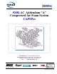
SMR-AC Addendum “A” Compressed Air Foam System CAFSPro Hale Products Inc. ◆ A Unit of IDEX Corporation 700 Spring Mill Avenue ◆ Conshohocken, PA 19428 U.S.A. Telephone: 610-825-6300 ◆ FAX: 610-825-6440 Web............www.haleproducts.
NOTICE ! Class1 cannot assume responsibility for product failure resulting from improper maintenance or operation. Class1 is responsible only to the limits stated in the product warranty. Product specifications contained in this manual are subject to change without notice. All Class1 products are quality components -- ruggedly designed, accurately machined, precision inspected, carefully assembled and thoroughly tested.
Adde ndum - Table of C ont ents ❑ Contents Page SMR-AC CAFSPro Installation Addendum Addendum: SMR-AC Installation........................................................................ 5 A.1 Unpacking ........................................................................................................................... 5 Lifting the System ...............................................................................................................................
❑ A dde ndum - Ta ble of Contents Contents - continued Page Notes _______________________________________________________________________ _______________________________________________________________________ _______________________________________________________________________ _______________________________________________________________________ _______________________________________________________________________ _______________________________________________________________________ ___________
SMR -AC Ins talla tion a nd Se tup ❑ Addendum: SMR-AC Installation This SMR-AC Installation Addendum is in addition to and is to be used in conjunction with the CAFSPro Installation Guide, Hale p/n: 029-0020-78-0. Additional installation is required by the builder / installer as the Oil Separator Tank must be externally mounted, requiring additional plumbing. A.1 UNPACKING The SMR-AC CAFSPro system is shipped primarily assembled on two skids.
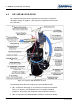
❑ SMR -AC Ins talla tion a nd Se tup WARNING - continued ! PLACE A BRACE, APPROXIMATELY 3’ (1 METER) BETWEEN THE LIFTING STRAPS / CHAINS TO PREVENT APPLYING EXCESSIVE PRESSURE TO THE MANIFOLDS AS THE SYSTEM IS LIFTED INTO PLACE. APPLY A STRAP AROUND THE FRONT SUCTION INLET AS SHOWN TO DEVELOP A THREEPOINT LIFT, MAKING SURE THE SYSTEM IS BALANCED. ALSO SEE FIGURE A-1: “LIFTING THE SMR-AC SYSTEM (THREE-POINT LIFT).” Figure A-1: Lifting the SMR-AC System (Three-Point Lift) A.
SMR -AC Ins talla tion a nd Se tup ❑ Whether mounting directly to the chassis, or constructing a separate bracket, accepted brackets must be used. Shock absorption is provided and must be included in any mounting modification. (See Figure A-2: “Shock Mounting.”) All mounting brackets must be constructed from structural angled steel, having minimum dimensions of 4” x 36” x 1/2” (102 x 914 x 13 mm). Use minimum 5/8”, Grade 8 bolts with flat washers and lock nuts.
❑ SMR -AC Ins talla tion a nd Se tup Attach female eye-bolts, 12 mm, to the top cross bracket mounting studs for lifting. Mount the separator tank having the inlet port sightly BELOW the compressor discharge port to ensure back-flush does not enter the compressor, which would severely damage the unit. (See Figure A-4: “Lifting Separator Tank.”) Mount the tank using 7/16”-14, Grade 8 screws, flat and lock washers and nuts.
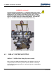
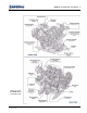
SMR -AC Ins talla tion a nd Se tup ❑ Figure A-5: Overview, SMR-AC System Connections Addendum - SMR-AC CAFSPro Installation Guide p/n: 029-0020-78-0 55
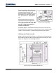
❑ SMR -AC Ins talla tion a nd Se tup A.4 OIL SEPARATOR TANK For a general overview of the oil separator tank connection, see Section “Drawing Package” on page 67. (See Figure A-6: “Separator Tank Installation Overview.”) Figure A-6: Separator Tank Installation Overview The following connections are made by the system builder/installer: ❑ (#1) Compressor discharge air / oil mixture to oil separator tank INLET. Use 1-1/2” (38 mm), wire reinforced hose. For example, Aeroquip FC350-24.
SMR -AC Ins talla tion a nd Se tup ❑ Use 1-1/4” (32 mm), wire reinforced hose for maximum air flow. For example, Aeroquip FC350-20. Note: Two check valves are provided in this discharge line to ensure water is not back-flushed into the oil separator tank. ❑ (#3) Oil separator tank DISCHARGE to heat exchanger. Use 7/8” (22 mm), wire reinforced hose. For example, Aeroquip FC35016. (See Figure A-6: “Separator Tank Installation Overview,” on page 56.) ❑ (#4) Air sensing valve to duplex gauge.
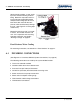
❑ SMR -AC Ins talla tion a nd Se tup Note: A minimum 1” (25.4 mm) connection is required to test the system per NFPA standards. A.5 AIR FILTER For reliable operation, the CAFS air filter must be located in a clean, freshair environment, usually in the dunnage area above the pump compartment. DO NOT damage the filter during assembly and be sure the mounting area offers protection.
SMR -AC Ins talla tion a nd Se tup ❑ (See Figure A-6: “Separator Tank Installation Overview,” on page 56.) Also see Figure A-7: “Depressurizing Valve Assembly” on page 57. A.7 FLUID LEVELS To meet various shipping regulations, oil within the pump gearbox and separator tank assemblies is drained prior to shipping from the factory. IMPORTANT ! AT INSTALLATION AND BEFORE OPERATION, ALL FLUIDS MUST BE ADDED TO THE APPROPRIATE LEVELS.
❑ SMR -AC Ins talla tion a nd Se tup Notes ______________________________________________________________________ ______________________________________________________________________ ______________________________________________________________________ ______________________________________________________________________ ______________________________________________________________________ ______________________________________________________________________ __________________________________________