
Installation Guide
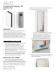


CB400 Cabinet Installation – v4
4. Set the cabinet aside and install mounting screws at
marks. Leave the head of the screw ½” clearance from
the back.
5. Hang enclosure on the screws and then mark the other
four screw locations at the tops of the middle and
bottom pairs of keyholes.
6. If cable access is to be from the rear, also mark the
relevant knockout locations, then remove the enclosure
and cut access holes for cables.
7. Secure the enclosure to wall using wood screws in the
remaining 4 keyholes and tighten the top screws.
OPTION 2 – Recessed Mounting
1. Fasten the cabinet to the sides of the studs using #8
screws rated for 100 lbs. (45 kg) loads using the 2 slots on
each of the cabinet side walls.
2. Adjust the depth of the cabinet position to ensure the
front face of the cabinet aligns with the surface of the
finished wall.
3. Insert and secure #8 mounting screws into the additional
4 flexing tabs on the top and bottom of the cabinet side
walls. These tabs will flex to mate securely with studs
even if not vertically aligned.
4. Securely tighten the mounting screws in the 4 slots.
REMOVE WIRING KNOCKOUTS & CONNECT CONDUIT
1. Select which knockouts will be used to route cabling in
and out of the cabinet.
2. Remove only the required knockouts needed for cable
routing.
3. Connect the appropriate conduit to the cabinet at the
open knockout locations.
ROUTE CABLING FROM POWER SUPPLY & GLASS
1. Route the approved cabling from the Halio system power
supply through the knockouts into the cabinet.
2. Connect the power supply cabling to the appropriate
terminals in the terminal block in the bottom of the
Component Cabinet.
3. Route the approved cabling from the Halio smart tinting
glass panels into the component cabinet through the
appropriate knockouts.
INSTALL ELECTRONICS & CONNECT WIRING
1. Mount each Tint Driver on the DIN-rail starting from the
bottom of the cabinet and moving up.
2. Mount the System Gateway in the top position on the
DIN rail.
3. Connect the appropriate glass driver cable to each Tint
Drivers using the provided 8-position connector.
4. Connect the appropriate power cables to each Tint Driver
and Gateway.
5. Turn on system power to the Component Cabinet
6. Once the Gateway and Tint Drivers are powered up, they
can be commissioned using the Halio software.
NOTE: See more details on Gateway and Driver installation
and system commissioning in the relevant guides.
MOUNT CABINET COVERS
1. Once commissioned, screw on the side, top and bottom
covers that restrict access to wiring connections.
2. Mount the hinged Halio door on the front of the cabinet.
TROUBLESHOOTING
For installation troubleshooting guides and questions,
please visit www.halioglass.com/support.
REGULATORY COMPLIANCE
This device meets the FCC and IC requirements for RF exposure in
public or controlled environments. The end user is advised to
maintain a distance of 20 cm from the controller and any personnel
to ensure compliance with RF exposure regulations.
Underwriters Laboratories, Inc.
UL Control No. xxxxx
[statement pending]