
Instructions / Assembly


12
R
F
X
U
F
X
R
U
A
B
C
X
F
R
A
B
C
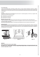
A1) Burners of the hob
1. Remove the grill, the caps and the burners from the worktop.
2. Lift the worktop.
3. Unscrew the screw “F” and remove the pipe “R”.
4. Unscrew the injectors (U) and replace them with those suitable for the gas used, supplied with the cooker. See TABLE 2.
5. The air is adjusted by means of the pipe “R” according to the value “X” given in TABLE 2 for the primary air opening.
Once regulation has been completed, secure the pipe ”R” with the screw “F”.
A2) Air adjustment
The air adjustment must be carried out with the burner ignited and the flame to the maximum.
Examples (Fig.10):
A) Flame with excess of air; it is small and thin. Move sleeve R forward.
B) Flame with lack of air; it is irregular with yellow streaks. Move sleeve R backward.
C) Normal fl ame: its colour is light blue.
Figure 8 Figure 9 Figure 10
B1) Burner in the oven
1. Remove the bottom shelf of the oven
2. Remove the fi xing screws to move the burner
3. Unscrew the injectors and replace it with one suitable for the gas used. See table 2.
4. Unscrew the screw “f”.
5. The burner air must be adjusted by means of the pipe “r” according to the value ”x” given in table 2 for the
“primary air opening”.
6. Once regulation has been completed, secure the pipe “r” with the screw “f”.
B2) Air adjustment
The air adjustment must be carried out with the burner ignited and the flame to the maximum.
Examples (Fig.12):
D) Flame with excess of air; it is small and thin. Move sleeve R forward.
E) Flame with lack of air; it is irregular with yellow streaks. Move sleeve R backward.
F) Normal fl ame: its colour is light blue.
Figure 11 Figure 12