
Instructions / Assembly


6
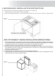
ANTI-TIP STABILITY DEVICE INSTALLATION INSTRUCTIONS
1. The anti-tip bracket have to be attached to rear wall, as show in Fig.4, before backguard installation. The dimension
for the bracket location from the fl oor have to be determined after range legs have been adjusted to the proper
installation height as show in the installation instructions and the range has been levelled.
2. Measure from the fl oor to the bottom of the anti-tip location on the back of the range.
3. Locate the two anti-tip bracket holes (dimension of the holes 15/64”(6mm)) on the wall at the measured dimension
plus 5/32”(4mm). The two anti-tip have to be placed close to the side of the range location (recommended
dimension is 1”(25,4mm from the sides).
4. Fix the two bracket on the wall.
5. Install backguard, as shown at the next part (see Install backguard chapter).
6. Adjust range legs 5/16”(8mm) shorter than the proper installation height. Slide in then the range against the wall.
Adjust range legs to the proper installation height.
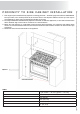
BACKGUARD INSTALLATION INSTRUCTION
Please follow the following installation instructions in sequence:
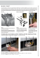
1. install base feet (see proper instruction Fig.3)
2. Place the backguard and fix it from bottom side with the two screw as shown in figure below.
Figure 3
Figure 4