
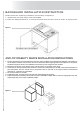
Instructions / Assembly

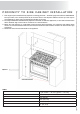


8
ELECTRICAL CONNECTION
The appliance shall be connected to a single phase electric line rated at 120/208Vac or
120/240Vac and 60Hz frequency.
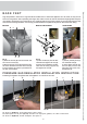
The appliance is equipped at the factory with a flexible hose . Inside the flexible hose you have
4 cables: grenn cable must be connected to the ground, white cable (NEUTRAL), red en black
cables: supply wire (L1 – L2). Check the electrical schetch available at the bottom in our in-
structions booklet
Electric power absorption of each model are shown in the Electrical and Gas Power Table en-
closed.
Before connecting the appliance to the electric network, follow the instructions below:
1. fuse and electric feeding installation of your home must support the load of the appliance (see registration label).
2. Power supply system must have an effi cient earth plate.
3. The outlet or multiple-switch, with a minimum1/8” (3mm) contact opening, has to be easily reached once the
appliance has been installed.
The appliance is supplied without outlet: you need a normal one proper for the electric load.
The power supply cable should not reach a 120°F temperature above the one surrounding.
GAS CONNECTION
All gas connections must be made according to national and local codes. This gas supply (ser-
vice) line must be the same size or grater than the inlet line of the appliance. This range uses a
½”NPT inlet. Sealant on all pipe joints must be resistive to LP gas.
1. Manual Shut-off Valve: This installer-supplied valve must be installed in the gas service line ahead of the appliance
in the gas stream and in a position where it can be reached quickly in the event of an emergency. The manual
shut-off valve shall be installed properly in order to be accessible when appliance is installed in defi nitive position.
In Massachusetts: A ‘T’ handle type manual gas valve must be installed in the gas supply line to this appliance.
2. Pressure Regulator
1. All heavy duty, commercial type cooking equipment must have a pressure regulator on the incoming service line
for safe and effi cient operation, since service pressure may fl uctuate with local demand. The pressure regulator is
supplied separately with the appliance; regulator has two female threads ½” NPT; it shall be installed properly in
order to be accessible when appliance is installed in defi nitive position.
2. This range can be used with Natural or LP/Propane gas. It is shipped from the factory adjusted for use with natural
gas. The orifi ce hoods must be screwed snug when LP/Propane gas is used(see LP/Propane conversion).
3. The appliance, its individual shut-off valve, and pressure regulator must be disconnected from the gas supply
piping system during any pressure testing of that system at pressure is in excess of 1/2psig(3.45kPa).
4. The appliance must be isolated from the gas supply piping system by closing its individual manual shut-off valve
during any pressure testing of gas supply piping system at test pressures equal to or less than 1/2psig(3.45kPa).
3. Flexible Connections:
1. If the unit is to be installed with fl exible couplings and/or quick disconnect fi ttings, the installer must use an heavy
duty, AGA design-certifi ed commercial fl exible connector of at least ½”(1.3cm)ID NPT(with suitable strain relieves)
in compliance with ANSI Z21.41 and Z21.69 standards.
2. In Massachusetts: The unit must be installed with a 36” (3-foot) long fl exible gas connector.
3. In Canada: CAN 1-6.10-88 metal connectors for gas appliances and CAN 1-6.9M79 quick disconnect device for
use with gas fuel.
CAUTION: Leak testing of the appliance shall be conducted according to the manufacturer’s instructions. Before placing the
oven into operation, always check for leaks with a soapy water solution of other acceptable method. DO NOT USE AN OPEN
FLAME TO CHECK FOR LEAKS!