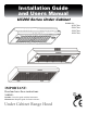
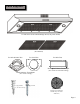
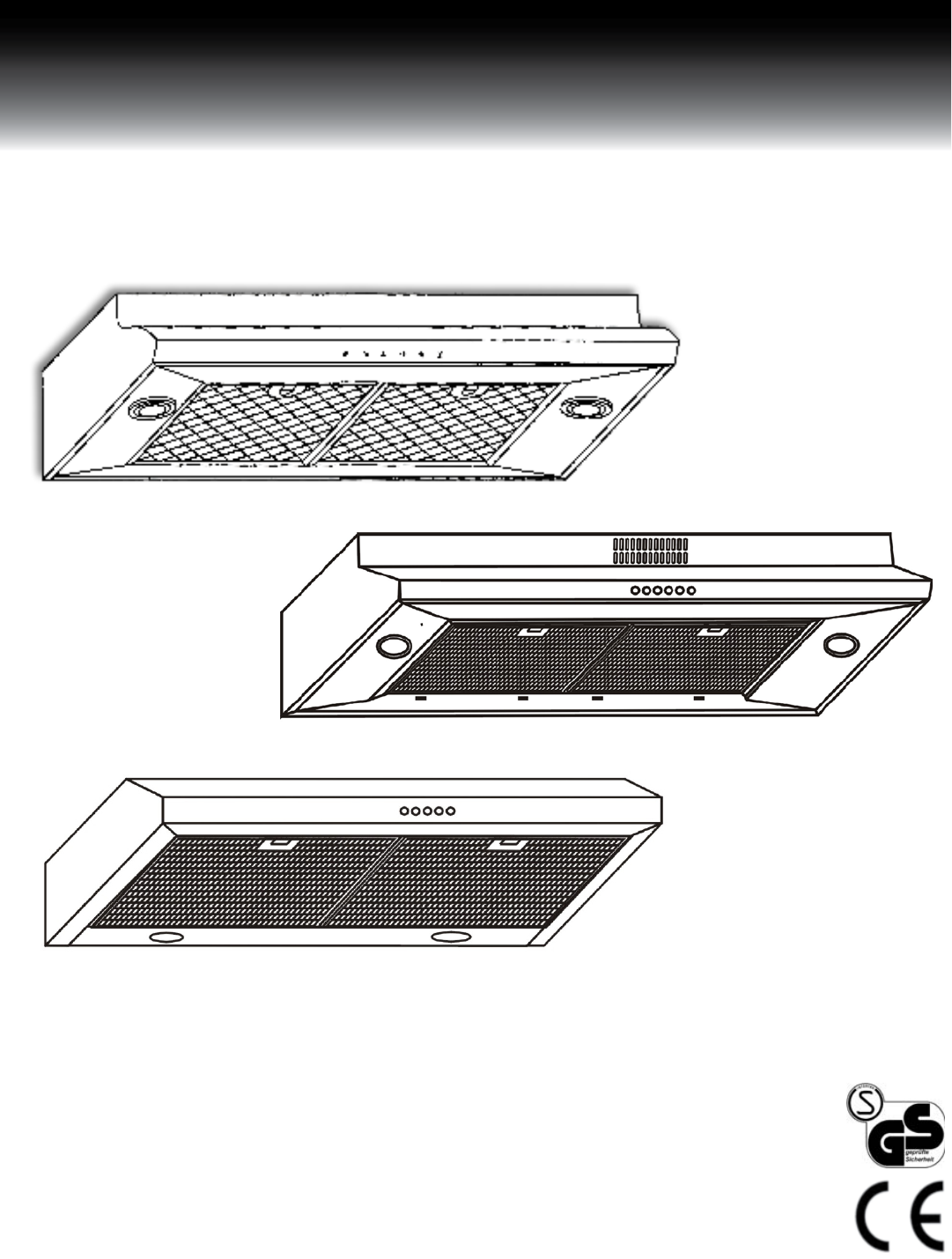
Installation Guide and Users Manual UC200 Series Under Cabinet Suitable for: 4100 Class 2000 Class 1900 Class 1800 Class IMPORTANT: Read and save these instructions. NOTICE: Installer: Leave this guide with the homeowner Homeowner: Keep this guide for future reference Under Cabinet Range Hood Rev. 1032u.
Important Safety Notice Read all Instructions before Installing and operating this appliance • • • • • The installation in this manual is intended for qualified installers, service technicians or persons with similar qualified background. Installation and electrical wiring must be done by qualified professionals and in accordance with all applicable codes and standards, including fire-rated construction. DO NOT attempt to install this appliance yourself.
Important Safety Notice Read all Instructions before Installing and operating this appliance • • • Clean ventilating fan frequently. Always use appropriate cookware and utensils size. Always use cookware appropriate for the size of the surface element. To reduce the risk of injury to persons in the event of a stove top grease fire: • • • SMOTHER FLAMES with a close-fitting lid, cookie sheet, or metal tray, then turn OFF the burner. BECAREFUL TO PREVENT BURNS.
Table of Contents INSTALLATION Tools needed....................................................3 Parts supplied...................................................4 Venting requirements.......................................5 Mount heights & clearance...........................5-6 Calculating vent system length.......................6 Venting methods & charcoal filters.................7 Ductless conversion & electrical requirements.8 Preparation......................................................
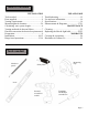
Parts Supplied: UC200 Series Under Cabinet Range Hood (vary with model) Aluminum Filters (Pre-Installed) for 1900 & 2000 Class for 4100 Class for 1800 Class Rectangular Exhaust/Vent Adapter Round Exhaust /VentAdapter (For vertical or horizontal venting) (For vertical venting) Qty: 4 PCS (For sheet rock only) Qty: 4 PCS Charcoal filter (Optional re-circulating kit available only on UC2002000 Class) Page 4
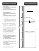
Venting Requirements • • • • • • • Height & Clearance Vent system must terminate to the outside (roof or side wall). DO NOT terminate the vent system in an attic or other enclosed area. DO NOT use 4” (10.2 cm) laundry-type wall caps. Use metal/aluminum vent only. Rigid metal/ aluminum vent is recommended. DO NOT use plastic vent. Always keep the duct clean to ensure proper airflow. Calculate the following figures before installation: 1. Distance from the floor to the ceiling. 2.
IMPORTANT: • A minimum of 6” round (standard for this range hood) or 3-1/4 x 10” rectangular duct (purchased separately) must be used to maintain maximum airflow efficiency. • Always use rigid type metal/aluminum ducts if available to maximize airflow when connecting to provided duct. • Please use Duct Run Calculation below to compute total available duct run when using elbows, transitions and caps. • ALWAYS, when possible, reduce the number or transitions and turns.
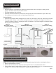
Venting Methods IMPORTANT: • • • • NEVER exhaust air or terminate duct work into spaces between walls, crawl spaces, ceiling, attics or garages. All exhaust must be ducted to the outside. Use metal/aluminum duct work only. Fasten all connections with sheet metal screws and tape all joints with certified Silver Tape or Duct Tape. Use caulking to seal exterior wall or roof opening around the cap. Venting Methods: • Vent work can terminate either through the roof or wall.
Ductless Conversion • • • Ductless conversion is intended for applications where an exhaust duct work is not possible to be installed. When converted, the hood functions as a purifying hood rather than an exhaust hood. Fumes and exhaust from cooking is drawn and filtered by a set of charcoal filters. The air is then purified and re-circulated back within the home. We recommend to ALWAYS exhaust air outside of the home by employing existing or installing new duct work, if possible.
Preparation WARNING Advanced Preparations: • Be familiar with the controls of the range hood by reading through Range Hood Operations, Page 13-14. • Place the range hood on a flat, stable surface. Connect the Excessive Weight range hood to a designated standard outlet and turn on the Require three or more person to move and range hood. Verify all operations of the range hood by refer- install this range hood. Spinal or other bodiring to Range Hood Operations, Page 13-14.
Installation Installations (refer to Page 4 for parts): Measure the distance between stove top and the bottom of range hood. A distance of 27” to 30” is recommended*. *Due to different ceiling height configurations, recommended height may not be applicable. 1. You have two ways (A: Vertical Venting, or B: Horizontal Venting) to mount this range hood: 1. Determine venting method as shown on Page 7 and proceed if you would like to vent vertically. 2.
Installation (Continued) Figure 3: Cabinet Bottom View UC200-4130W Wood Filler Strips (Not included) Hood Mounting Screws Electrical Access Opening Wall Centerline UC200-2000 Class Wood Filler Strips (Not included) Hood Mounting Screws Electrical Access Opening Wall Centerline UC200-1900 Class Wood Filler Strips (Not included) Electrical Access Opening Wood Filler Strips (Not included) Wall Centerline UC200-1800 Class Electrical Access Opening Centerline Hood Mounting Screws Figure 4: Electric
Installation (Continued) Figure 5: Cabinet Front View UC200-4130W Centerline Hood Mounting Screws UC200-1900 Class Centerline Hood Mounting Screws UC200-1800 Class Centerline Electrical Wire Opening Electrical Wire Opening Figure 6: Electrical wires through rear opening Page 12
Range Hood Operations Control Panel Layout and Buttons Configurations: 1. Electronic Control Filter Clean Reminder Light Control Quiet Speed Low Speed High Speed Power Control (On/Off) This range hood is equipped with five electronic controls, a powerful centrifugal squirrel cage motor with two aluminum filters, two bright 20W~12V or 40W~120/240V halogen lights and a filter clean reminder.
Range Hood Operations (Continued) Control Panel Layout and Buttons Configurations: Turning Fan OFF: The 3-minute power-off delay function will only turn OFF fans. The light settings will not be affected by the delay function. Three-Minute Delay • While the fans are operating, press Power Control (On/Off) button once, the Power Control LED will flash and fans will turn OFF after 3-minutes. • During this 3-minutes delay, changing speeds will not affect the countdown.
Troubleshooting 1. If the range hood or halogen light does not operate after installation: • • Check if the range hood has been plugged in, make sure that all power has been turned back ON, fused not blown and all electrical wiring are properly connected. Swap out light assembly to working ones to determine whether it is caused by defective bulbs. See Replacing the light bulbs on Page 22. 2.
Use and Care Information Operations: • • • • • Read and understand all instructions and warnings in this manual before operating the appliance. Save these instructions for future reference. Always leave safety grills and filters in place. Without these components, operating blowers could catch on to hair, fingers and loose clothing. NEVER dispose cigarette ashes, ignitable substances, or any foreign objects into blowers. NEVER leave cooking unattended.
Measurements and Diagrams • All measurements in parenthesis are in millimeter. • All inch measurements are converted from millimeters, thus inch measurements are estimated.
• • All measurements in parenthesis are in millimeter. All inch measurements are converted from millimeters, thus inch measurements are estimated.
• • All measurements in parenthesis are in millimeter. All inch measurements are converted from millimeters, thus inch measurements are estimated.
• • All measurements in parenthesis are in millimeter. All inch measurements are converted from millimeters, thus inch measurements are estimated.
Circuit Diagram: UC200-4100 Class GREEN UC200-18/19/2000 Class NOTE: Wiring Diagram shown above with GU10 light configuration. A transformer is required for MR16/J4 Lights.
Maintenance SAFETY WARNING: Never put your hand into area housing the fan while the fan is operating! For optimal operation, clean range hood & all filter/oil container regularly. Regular care will help preserve the range hood’s performance & appearance. WARNING Hazard of Burns! Light bulb become extremely hot when turned on. DO NOT touch bulb until switched off and cooled. Touching hot bulbs could cause serious burns.
WARNING Maintenance (Continued) Hazard of Burns! Replacing J4 Type Halogen Light Bulb: • When the range hood uses J4 type halogen light bulb: 20W 12V. • Make sure the range hood is unplugged or turn OFF breaker and the lights are cool to touch. • Place a small flat-head screwdriver between light housing and lens cover, carefully and gently pry up the lens cover. • Remove the old halogen light bulb by pulling in the direction of wavy arrow. Do not touch the new light bulb with bare hands.
Warranty TO OBTAIN SERVICE UNDER WARRANTY: You must present proof of original purchase date. Please provide an original dated proof of purchase (sales receipt / invoice) in order to obtain service under warranty. One Year Parts Warranty: For one year from the date of original purchase, your local reseller will provide free of charge, non-consumable replacement parts or components that failed due to manufacturing defects.
Disclaimer Carefully inspect all items for damages before accepting delivery. note any damages on the freight bill or express receipt. request name and signature of the carrier’s agent and keep copy to support your claim. Upon acceptance of items, owner assumes responsibility for its safe arrival. Report damages to the carrier and file a claim immediately. Failure to do so may result in the denial of your claim. The carrier will furnish you with necessary forms for filing a claim.
Aus-Tex Appliance 113 Industrial Blvd #D Austin, TX 78745 Tel: 512.444.